Steel plate composite shear wall of built-in cross-pulling screws and construction method of steel plate composite shear wall

A combined shear wall and pair-pulling screw technology, applied in the direction of walls, building components, buildings, etc., can solve the problems of cumbersome construction procedures, insufficient lateral rigidity of concrete pouring, and difficulty in ensuring the smoothness of the wall surface, so as to achieve enhanced connection performance, The effect of ensuring flatness and preventing deformation

Pending Publication Date: 2019-06-18
CISDI ENG CO LTD
View PDF11 Cites 1 Cited by
  • Summary
  • Abstract
  • Description
  • Claims
  • Application Information

AI Technical Summary

Problems solved by technology

[0004] In view of this, in order to solve the problem of insufficient lateral rigidity in the transportation and concrete pouring of the double-layer steel plate composite shear wall structure in the prior art, the present invention provides a construction method and construction method of the steel plate composite shear wall with built-in pull-screw , the built-in tension screw structure can increase the connection performance between the steel plate and concrete, and solve the problems of cumbersome on-site construction procedures and difficulty in ensuring the smoothness of the traditional tension screw

Method used


Image

  • Steel plate composite shear wall of built-in cross-pulling screws and construction method of steel plate composite shear wall
  • Steel plate composite shear wall of built-in cross-pulling screws and construction method of steel plate composite shear wall
  • Steel plate composite shear wall of built-in cross-pulling screws and construction method of steel plate composite shear wall

Examples


Embodiment 1

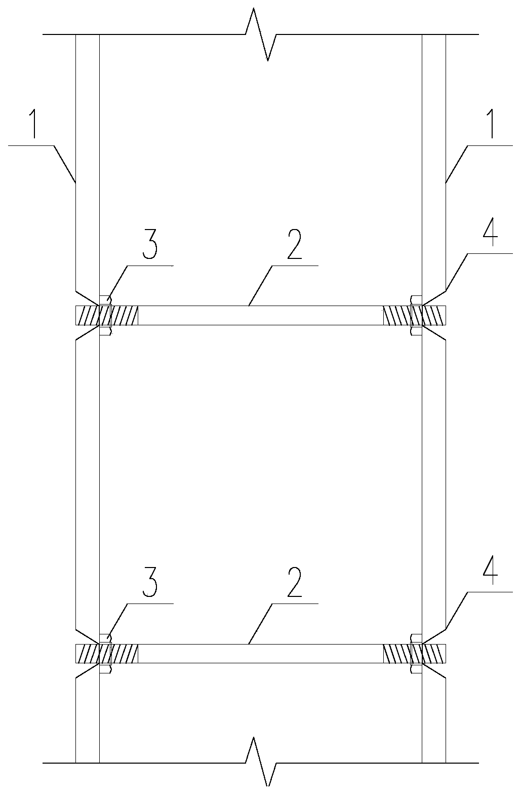
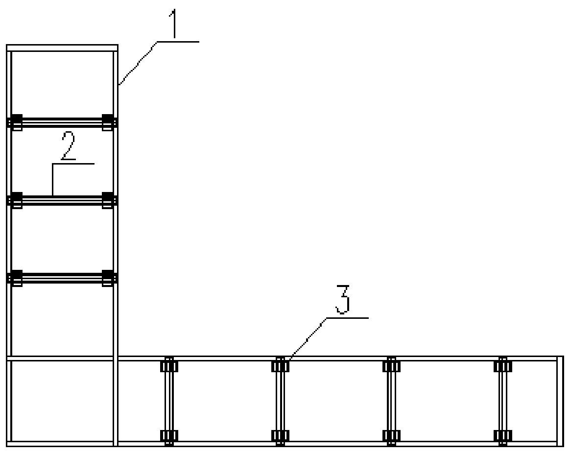
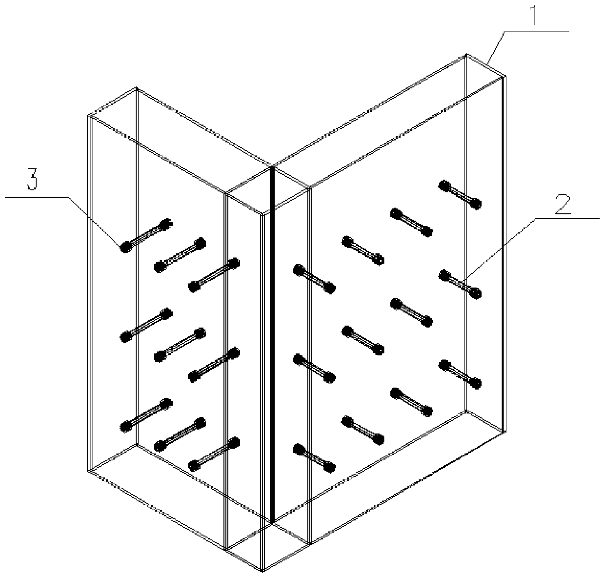
[0026] Such as Figure 1~3 The steel plate composite shear wall with built-in tension screw includes two corresponding steel plate composite shear wall steel plates 1, tension screw 2, limit nut 3 and plug welding hole 4, and the composite shear wall steel plate 1 is A number of corresponding plug welding holes 4 are evenly opened, and the positions of the plug welding holes 4 on the combined shear wall steel plate 1 correspond one by one, and the plug welding holes 4 are pierced with a pull screw 2 for constraining the combined shear wall steel plate 1 During the processing of the combined shear wall steel plate 1 in the factory, the pull screw 2 is built into the two combined shear wall steel plates 1, and a pair of pull screws 2 on the inner side of the combined shear wall steel plate 1 are set for fixing. The limit nut 3 of the pulling screw 2 is used to adjust the thickness and verticality of the steel plate composite shear wall during the processing through the limit nut...

Embodiment 2

[0028] The difference between embodiment 2 and embodiment 1 is that the plug welding hole 4 is in an inverted cone shape, and the outer diameter of the plug welding hole 4 is larger than the inner diameter of the plug welding hole 4 .

[0029] A construction method of a steel plate composite shear wall with built-in tension screws, comprising the following steps:

[0030] A. Put the combined shear wall steel plate 1 on one side of the steel plate combined shear wall flatly on the ground, screw two limit nuts 3 on the pull screw 2, and then place all the pull screws 2 of the steel plate wall in alignment On the combined steel plate shear wall steel plate 1 on the ground, spot-weld the limit nut 3 and the combined shear wall steel plate 1 on the ground after alignment adjustment;

[0031] B. Adjust the position of the limit nut 3 at the other end of the pull screw 2 according to the thickness and verticality of the steel plate combined shear wall, and connect the plug welding ho...


PUM


Abstract

The invention belongs to the field of building structure engineering, and relates to a steel plate composite shear wall of built-in cross-pulling screws and a construction method of the steel plate composite shear wall. The steel plate composite shear wall includes two corresponding composite shear wall steel plates, the cross-pulling screws, limiting nuts and plug welding holes, wherein the composite shear wall steel plates are evenly provided with multiple corresponding plug welding holes, the cross-pulling screws used for connecting the composite shear wall steel plates are arranged in theplug welding holes in a penetrating mode, a pair of limiting nuts used for mounting and positioning the composite shear wall steel plates sleeve the cross-pulling screws on the inner sides of the composite shear wall steel plates, and the built-in cross-pulling screws provides enough lateral rigidity for transportation of the steel plate composite shear wall and concrete pouring. According to thesteel plate composite shear wall, flatness of the outer sides of the composite shear wall steel plates can be guaranteed through the structure and the construction method.

Description

technical field [0001] The invention belongs to the field of building structure engineering, and relates to a steel plate composite shear wall with built-in tension screws and a construction method thereof. Background technique [0002] The double-layer steel plate composite shear wall structure is more and more widely used in the design of high-rise buildings. Its structural feature is that the double-layer steel plate sandwiches the internal concrete, which can realize the coordination between the steel plate and the concrete, and give full play to the structural characteristics of the steel structure and concrete. During the construction of the double-layer steel plate combined shear wall, the inner cavity concrete can be directly poured after the steel plate wall is positioned and installed. Stiffeners, built-in panels, and tension bolts and other structural forms. [0003] The built-in stud setting and T-shaped stiffeners can increase the connection performance between...

Claims


Application Information

Patent Timeline
Patent Type & Authority Applications(China)
IPC IPC(8): E04B2/56E04B2/84E04B2/86
Inventor 沈琪雯薛尚铃胡朝晖罗福盛邓玉孙陶修程振宇余周李芳静魏佳
Owner CISDI ENG CO LTD
Why Eureka
Try Eureka