Rear tilt angle pumping unit

A technology of pumping unit and driving mechanism, which is applied in the direction of mining fluid, wellbore/well parts, earthwork drilling and production, etc. It can solve problems such as unreasonable structure, difficult long stroke, complicated principle, etc., and achieve simple structure and reduce steel The effect of simple dosage and operation principle

Pending Publication Date: 2019-06-18
李兆胜
View PDF7 Cites 0 Cited by
  • Summary
  • Abstract
  • Description
  • Claims
  • Application Information

AI Technical Summary

Problems solved by technology

However, the applicant found in the actual use process that the structure of these patented technologies is still unreasonable, and the principle is relatively complicated, the weight is heavy, and it is difficult to truly realize the long stroke smoothly.

Method used


Image

  • Rear tilt angle pumping unit
  • Rear tilt angle pumping unit
  • Rear tilt angle pumping unit

Examples


Embodiment 1

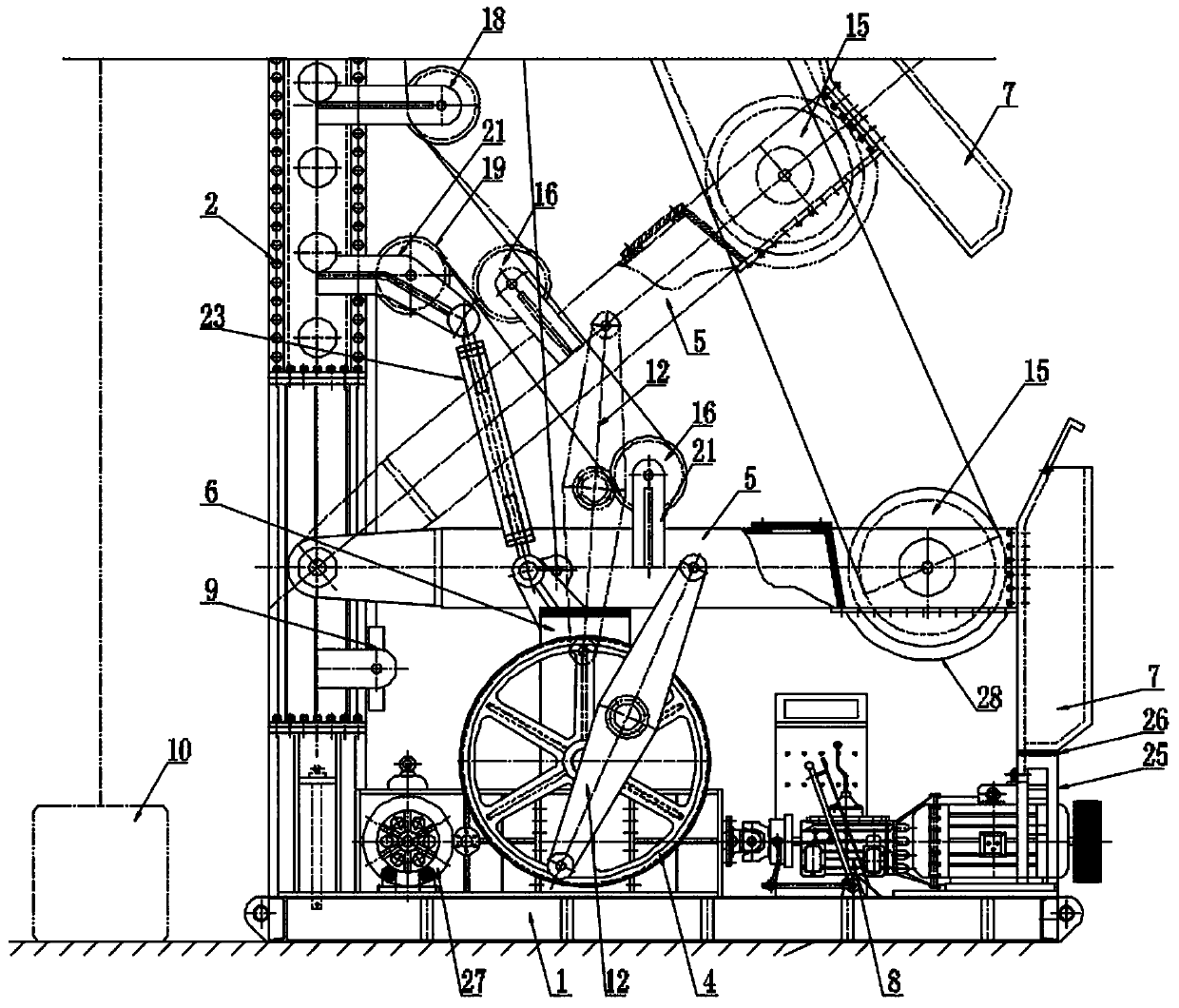
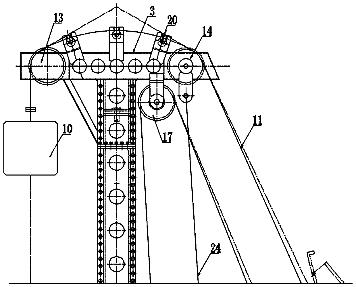
[0033] This embodiment discloses a rear swing angle pumping unit, which includes a base 1, a column 2, a boom 3, a power wheel 4, a driving mechanism 8, a swing arm 5, a support frame 6, a counterweight box 7, a rope drum, and a stable rope 9, rope hanger 10 and steel rope 11, the lower end of the column 2 is fixed on the base 1, the upper end is fixedly connected with the boom 3, one end of the swing arm 5 is movably connected to the column 2, and the other end is connected with the matching The heavy box 7 is fixedly connected; the support frame 6 and the driving mechanism 8 are fixed on the base 1, and the power wheel 4 is symmetrically fixed on both sides of the support frame 6 and driven by the drive mechanism 8; the power wheel 4 is connected eccentrically There is a connecting rod 12, one end of the connecting rod 12 is movably connected with the power wheel 4, and the other end is movably connected with the middle part of the swing arm 5, the rope stabilizer 9 is fixed ...

Embodiment 2

[0044] This embodiment discloses a rear swing angle pumping unit, which includes a base 1, a column 2, a boom 3, a power wheel 4, a driving mechanism 8, a swing arm 5, a support frame 6, a counterweight box 7, a rope drum, and a stable rope 9, rope hanger 10 and steel rope 11, the lower end of the column 2 is fixed on the base 1, the upper end is fixedly connected with the boom 3, one end of the swing arm 5 is movably connected to the column 2, and the other end is connected with the matching The heavy box 7 is fixedly connected; the support frame 6 and the driving mechanism 8 are fixed on the base 1, and the power wheel 4 is symmetrically fixed on both sides of the support frame 6 and driven by the drive mechanism 8; the power wheel 4 is connected eccentrically There is a connecting rod 12, one end of the connecting rod 12 is movably connected with the power wheel 4, and the other end is movably connected with the middle part of the swing arm 5, the rope stabilizer 9 is fixed ...

Embodiment 3

[0051] This embodiment discloses a rear swing angle pumping unit, which includes a base 1, a column 2, a boom 3, a power wheel 4, a driving mechanism 8, a swing arm 5, a support frame 6, a counterweight box 7, a rope drum, and a stable rope 9, rope hanger 10 and steel rope 11, the lower end of the column 2 is fixed on the base 1, the upper end is fixedly connected with the boom 3, one end of the swing arm 5 is movably connected to the column 2, and the other end is connected with the matching The heavy box 7 is fixedly connected; the support frame 6 and the driving mechanism 8 are fixed on the base 1, and the power wheel 4 is symmetrically fixed on both sides of the support frame 6 and driven by the drive mechanism 8; the power wheel 4 is connected eccentrically There is a connecting rod 12, one end of the connecting rod 12 is movably connected with the power wheel 4, and the other end is movably connected with the middle part of the swing arm 5, the rope stabilizer 9 is fixed ...


PUM


Abstract

The invention discloses a rear tilt angle pumping unit, which includes a base, a vertical column, a boom, power wheels, a driving mechanism, a swing arm, a support frame, a weight box, a rope roll, arope stabilizer, a beam hanger and a steel rope. The lower end of the vertical column is fixed to the base, the upper end of the vertical column is fixedly connected with the boom, and the two ends ofthe swing arm are connected with the vertical column and the weight box correspondingly; the support frame and the driving mechanism are both fixed to the base, and the power wheels are fixed to thetwo sides of the support frame; the power wheels are eccentrically connected with a connecting rod for being movably connected with the swing arm, and the rope stabilizer is fixed to the vertical column; and the rope roll includes a first rope roll, a second rope roll, a third rope roll, a fourth rope roll, a fifth rope roll, a sixth rope roll and a seventh rope roll, one end of the steel rope isconnected with the beam hanger, and the other end of the steel rope is connected to the rope stabilizer after successively bypassing the first rope roll, the second rope roll, the third rope roll, thefourth rope roll, the fifth rope roll, the sixth rope roll and the seventh rope roll. The rear tilt angle pumping unit can realize smooth reversing in the whole oil pumping process, and meanwhile, long-stroke oil pumping can be easily realized.

Description

technical field [0001] The invention belongs to the technical field of petroleum exploitation, and in particular relates to a back swing angle oil pumping unit. Background technique [0002] At present, in the field of oil exploitation technology, beam pumping units or broadband pumping units are generally used to pump oil, but beam pumping units have a huge It is becoming more and more difficult to meet the needs of existing deep wells. When the broadband pumping unit is in use, its motor needs to change the direction of rotation every minute, especially for high-power pumps, which has a very large impact on the power grid and is likely to cause grid distortion. [0003] In the field of pumping units, the current difficulty is: how to increase the stroke of the pumping unit to 4m, 6m, 8m, 10m, 12m, etc. under the premise of ensuring sufficient torque and stable high-point commutation. Among them, the applicant has applied for the names of: wide swing angle pumping unit (n...

Claims


Application Information

Patent Timeline
Patent Type & Authority Applications(China)
IPC IPC(8): E21B43/00
Inventor 李兆胜
Owner 李兆胜
Why Eureka
Try Eureka