Water leakage protection device of electric ball valve

A technology of water leakage protection and electric ball valve, which is applied in the direction of valve device, valve operation/release device, valve details, etc. It can solve the problems of power failure, large initial rotation torque of ball valve, and failure of internal driver to drive ball valve, etc.

Active Publication Date: 2019-06-18
宁波三胜智慧电子有限公司
View PDF8 Cites 0 Cited by
  • Summary
  • Abstract
  • Description
  • Claims
  • Application Information

AI Technical Summary

Problems solved by technology

If there is no flood or power failure for a long time, after the ball valve does not rotate for a long time, once flood or power failure occurs, the initial rotational torque of the ball valve will be very large, which will cause the

Method used


Image

  • Water leakage protection device of electric ball valve
  • Water leakage protection device of electric ball valve
  • Water leakage protection device of electric ball valve

Examples


Embodiment 1

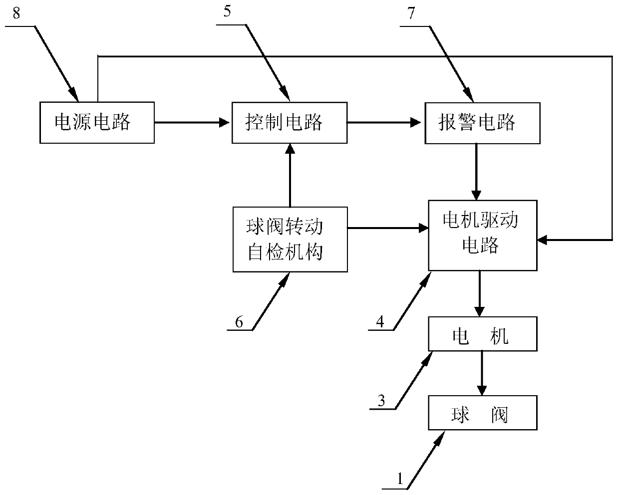
[0038] Example one: such as figure 1 As shown, a water leakage protection device for an electric ball valve includes a ball valve 1, a motor 3 for driving the switch of the ball valve 1, and a motor drive circuit 4 for driving the motor 3 forward and reverse, and also includes a control circuit 5 and a ball valve rotation self-check Mechanism 6, alarm circuit 7, and power supply circuit 8 for supplying power to the entire device. The control circuit 5 regularly controls the motor drive circuit 4 to drive the motor 3 to rotate in the forward or reverse direction. The ball valve rotation self-checking mechanism 6 is used to detect whether the ball valve 1 is rotating. It is normal, and the detected signal is fed back to the control circuit 5, and the alarm circuit 7 is connected to the control circuit 5. The control circuit 5 judges whether the alarm circuit 7 gives an alarm based on the signal fed back by the ball valve rotation self-checking mechanism 6.

[0039] In this specific ...

Embodiment 2

[0047] The second embodiment: the other structure is the same as that of the first embodiment, the difference lies in: Figure 8-13 As shown, the device also includes an upper housing 9 and a lower housing 10. A downwardly recessed motor mounting seat 101 is provided on one side of the lower bottom surface of the lower housing 10, the motor 3 is embedded in the motor mounting seat 101, and the ball valve 1 includes A mounting base plate 12 is fixedly connected to the other side of the lower housing 10. A plurality of columnar bodies 13 and reinforcing bosses 14 extending upward and downward are arranged on the lower bottom surface of the other side of the lower housing 10. The mounting base plate 12 is provided with a first limiting groove 151 that matches the column 13; the mounting base plate 12 is provided with a second limiting groove 152 that matches with the reinforcing boss 14, and the column 13 is provided with up and down through The upper mounting hole 16 is provided ...


PUM


Abstract

The invention discloses a water leakage protection device of an electric ball valve. The water leakage protection device comprises a control circuit, a ball valve rotation self-checking mechanism, analarm circuit and a power supply circuit which is used for supplying power to the whole device. The control circuit controls a motor driving circuit to drive a motor to rotate forwards or rotate reversely to be reset. The ball valve rotation self-checking mechanism is used for detecting whether the ball valve rotates normally or not and sending detected signals to the control circuit. The alarm circuit is connected with the control circuit. The control circuit judges whether an alarm is to be given by the alarm circuit or not according to the signals provided by the ball valve rotation self-checking mechanism. Once any problem occurs, a user can be reminded of timely overhauling, so that the ball valve can be normally and quickly driven by the motor to be closed under the condition that flood disasters of the ball valve did not happen for a long time but occur suddenly or outage happens. It is ensured that the ball valve can be normally closed when any flood disaster or outage happens.

Description

Technical field [0001] The invention relates to the technical field of an electric ball valve, in particular to a water leakage protection device of an electric ball valve. Background technique [0002] Electric ball valve is an important actuator in industrial automation control system. It is widely used in petroleum refining, long-distance pipelines, chemical industry, papermaking, pharmaceuticals, water conservancy, electric power, municipal administration, steel and other industries, and occupies a pivotal position in the national economy. The electric ball valve is equipped with a water leakage protection actuator. When a flood occurs, the power is cut off, and the water leakage protection actuator drives the ball valve to shut off the water source. If there is no flood or power failure for a long time, then after the ball valve does not rotate for a long time, once a flood or power failure occurs, the initial turning torque of the ball valve will be very large, which will ...

Claims


Application Information

Patent Timeline
IPC IPC(8): F16K31/04F16K37/00
Inventor 王兆军王娟邵浩洵
Owner 宁波三胜智慧电子有限公司
Why Eureka
Try Eureka