Adaptive-centering optical lens mounting device and optical element interval control method

A technology of optical lens and mounting device, which is applied in the direction of optical elements, mounting, optics, etc., can solve problems such as complex processing and manufacturing difficulties, avoid excessive drop in centering accuracy, reduce the impact of imaging quality, and make surface processing and manufacturing easy Effect

Pending Publication Date: 2019-06-18
HAINAN UNIVERSITY
View PDF11 Cites 2 Cited by
  • Summary
  • Abstract
  • Description
  • Claims
  • Application Information

AI Technical Summary

Problems solved by technology

Therefore, the applicant proposed to change the contact part into an arc surface in another patent application. Although the function of centering and positioning has been achieved, the processing and manufacturing are more complicated and difficult.

Method used


Image

  • Adaptive-centering optical lens mounting device and optical element interval control method
  • Adaptive-centering optical lens mounting device and optical element interval control method
  • Adaptive-centering optical lens mounting device and optical element interval control method

Examples


Embodiment Construction

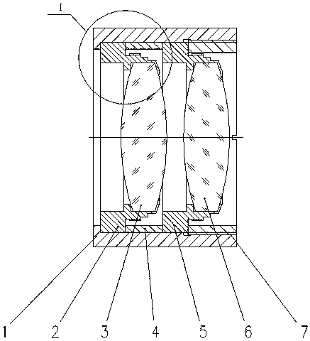
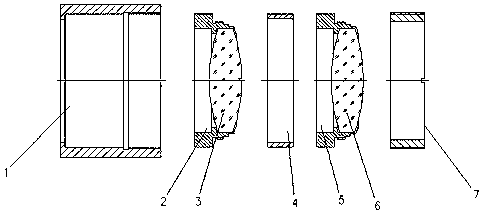
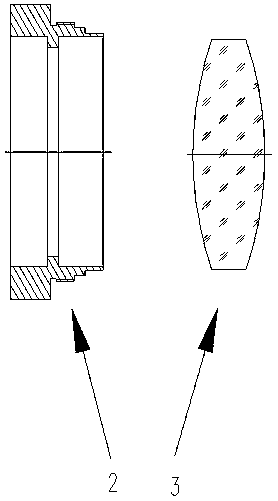
[0031] like Figure 5-8 As shown, this self-adaptive centering optical lens installation device, the optical lens includes: a lens barrel 1, a first roll edge mirror base 2, a first optical element 3, a spacer 4, a second roll edge mirror base 5, a first Two optical elements 6, pressure ring 7;

[0032] The first optical element 3 is assembled on the first roll edge mirror base 2, the second optical element 6 is assembled on the second roll edge mirror base 5, the first roll edge mirror base 2, the spacer 4, the second roll edge mirror base 5. Put them into the lens barrel 1 in turn, and fasten them in the lens barrel through the thread of the pressure ring 7;

[0033] The left side of the first roll side mirror base (2) is a cylinder, the longitudinal section of the cylinder is an isosceles trapezoid, and the cylinder and the lens barrel (1) are in line contact; the left side of the second roll side mirror base (5) It is a cylinder, the longitudinal section of the cylinder ...


PUM

PropertyMeasurementUnit
Tilt angleaaaaaaaaaa

Abstract

Provided is an adaptive-centering optical lens mounting device, which can ensure centering of an optical lens in impact test, avoid excessive loss of centering accuracy and reduce impact on the imaging quality of an optical lens; and compared with a device, the contact portion of which is a cambered surface, the device is easier to manufacture and process. A first optical element (3) is mounted ona first roller side mirror base (2); a second optical element (6) is mounted on a second roller side mirror base (5); the first roller side mirror base (2), a spacer ring (4) and the second roller side mirror base (5) are arranged in a lens cone (1) in sequence, and are fixedly arranged in the lens cone through screw thread of a pressing ring (7); the left side of the first roller side mirror base (2) is a cylinder, wherein the longitudinal section of the cylinder is isosceles trapezoid, and the cylinder and the lens cone (1) are in line contact; and the left side of the second roller side mirror base (5) is a cylinder, wherein the longitudinal section of the cylinder is isosceles trapezoid, and the cylinder and the spacer ring (4)are in line contact. The invention also provides an optical element interval control method.

Description

technical field [0001] The invention belongs to the technical field of optical equipment, and in particular relates to an adaptive centering optical lens mounting device, which is mainly used for ensuring the re-centering positioning of the optical lens in an impact test, and also relates to the adaptive centering optical lens A method of controlling the spacing of optical elements in a mounting device. Background technique [0002] With the development of society and the advancement of science and technology, the application of optical lenses has become more and more extensive, and optical lenses can be seen everywhere in industry and agriculture. Optical lenses are an essential piece of equipment in one of the hottest fields of virtual reality today. The main function of an optical lens is imaging. To achieve excellent imaging quality, it is generally necessary to use multiple optical components to form an optical lens. Many times, the centers of these optics need to be ...

Claims


Application Information

Patent Timeline
IPC IPC(8): G02B7/02
CPCY02P40/57
Inventor 刘晓梅柳华曹扬马小娟
Owner HAINAN UNIVERSITY
Why Eureka
Try Eureka