Pipeline pre-cooling system

A pre-cooling and pipeline technology, applied in the direction of pipeline heating/cooling, pipes/pipe joints/fittings, mechanical equipment, etc., can solve the problem of increased resistance to low-temperature medium flow, poor pre-cooling operation effect, and inability to increase pre-cooling flow To improve the pre-cooling effect and achieve the effect of pre-cooling the transmission pipeline

Pending Publication Date: 2019-06-21
CIMC ENRIC ENGINEERING TECHNOLOGY CO LTD
View PDF0 Cites 0 Cited by
  • Summary
  • Abstract
  • Description
  • Claims
  • Application Information

AI Technical Summary

Problems solved by technology

However, the low-temperature medium will gradually vaporize during the flow of the ship unloading pipeline, and the vaporized gas accumulates at the high point of the ship unloading pipeline, forming a liquid column in the riser of the pipeline climbing section, thus

Method used


Image

  • Pipeline pre-cooling system
  • Pipeline pre-cooling system
  • Pipeline pre-cooling system

Examples


Example Embodiment

[0034] Typical implementations embodying the features and advantages of the present invention will be described in detail in the following description. It should be understood that the present invention can have various changes in different implementations, which do not depart from the scope of the present invention, and the descriptions and diagrams therein are essentially for illustrative purposes, rather than limiting this invention.

[0035] In order to further illustrate the principle and structure of the present invention, the preferred embodiments of the present invention will now be described in detail with reference to the accompanying drawings.
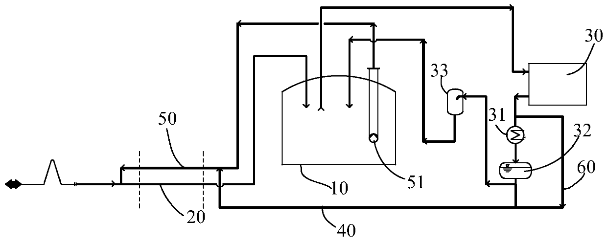
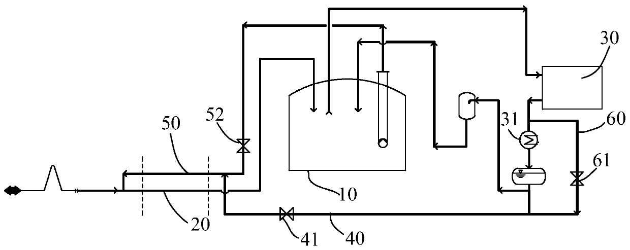
[0036] The present invention provides a pipeline pre-cooling system. See figure 1 , The pipeline pre-cooling system includes a low-temperature storage tank 10, a transmission pipeline 20, a compressor 30, and a booster pipeline 40. The cryogenic storage tank 10 has an accommodation cavity for accommodating the first medium; one...


PUM


Abstract

The invention provides a pipeline pre-cooling system. The pipeline pre-cooling system comprises a low-temperature storage tank, a transferring pipeline, a compressor and a pressurizing pipeline; one end of the transferring pipeline communicates with a containing cavity of the low-temperature storage tank, and the other end of the transferring pipeline is used for being connected with external equipment; the compressor is provided with an air inlet end, the air inlet end communicates with the containing cavity, and the compressor is used for compressing a gaseous first medium input from the airinlet end to form a second medium; and one end of the pressurizing pipeline is connected with the compressor, the other end of the pressurizing pipeline communicates with the transferring pipeline, and the pressurizing pipeline is used for transferring the second medium into the transferring pipeline for pre-cooling of the transferring pipeline. When the high-pressure second medium is introducedinto the transferring pipeline, the second medium can be vaporized rapidly, strong driving force is generated in the transferring pipeline to overcome the resistance caused by pipeline routes and liquid plugging in the pipelines, and thus the purpose of pre-cooling of the transferring pipeline is realized.

Description

technical field [0001] The invention relates to the field of low-temperature medium transportation, in particular to a pipeline precooling system. Background technique [0002] At present, when transporting cryogenic media by sea, such as cryogenic liquefied hydrocarbons, it is necessary to transport the cryogenic media on board to cryogenic storage tanks through unloading pipelines. When unloading low-temperature media, in order to avoid excessive stress on the pipeline caused by the low temperature of the material during unloading, the unloading pipeline must be pre-cooled before unloading. The pre-cooling operation of the unloading pipeline is directly related to the safety of the unloading system. [0003] However, in practical applications, due to the long distance between the cryogenic storage tank and the ship unloading dock, and the need to pass through multiple pipe racks with large height differences along the way, the pre-cooling process of the prior art ship unl...

Claims


Application Information

Patent Timeline
IPC IPC(8): F16L53/70
Inventor 张耀琴戴庆徐玲芳
Owner CIMC ENRIC ENGINEERING TECHNOLOGY CO LTD
Why Eureka
Try Eureka