

Heat storage type electric heater
An electric heater and heat storage technology, which is applied in the field of electric heaters, can solve the problems of fast decay of heat release rate and achieve the effects of slowing down heat release rate, increasing heat release area, and improving heat release comfort
- Summary
- Abstract
- Description
- Claims
- Application Information
AI Technical Summary
Problems solved by technology
Method used
Image

Examples
Embodiment Construction
[0037] The technical solutions of the present invention will be clearly and completely described below in conjunction with the accompanying drawings. Apparently, the described embodiments are some embodiments of the present invention, not all of them. Based on the implementation manners in the present invention, all other implementation manners obtained by persons of ordinary skill in the art without making creative efforts belong to the scope of protection of the present invention. In addition, the technical features involved in the different embodiments of the present invention described below may be combined with each other as long as there is no conflict with each other.
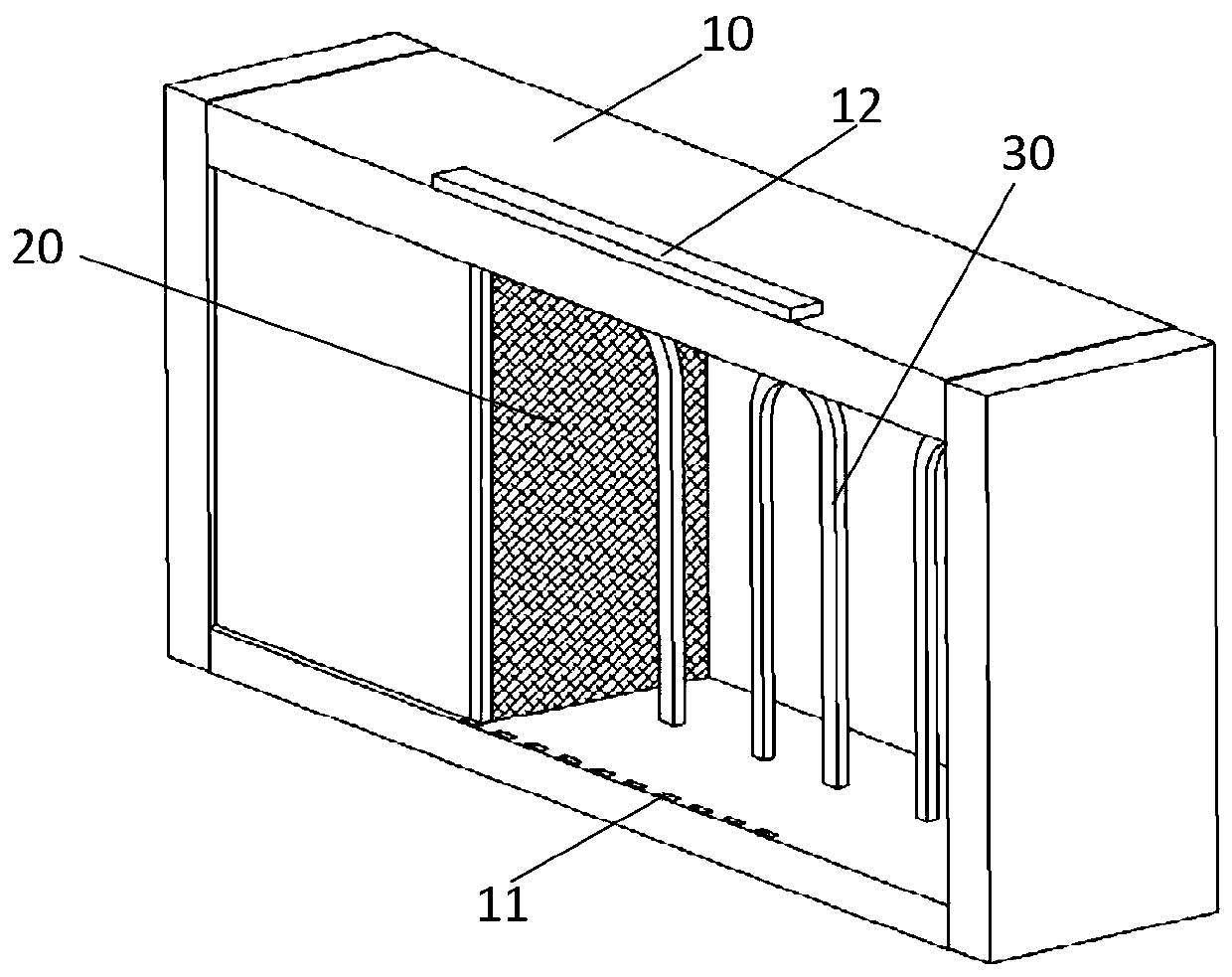
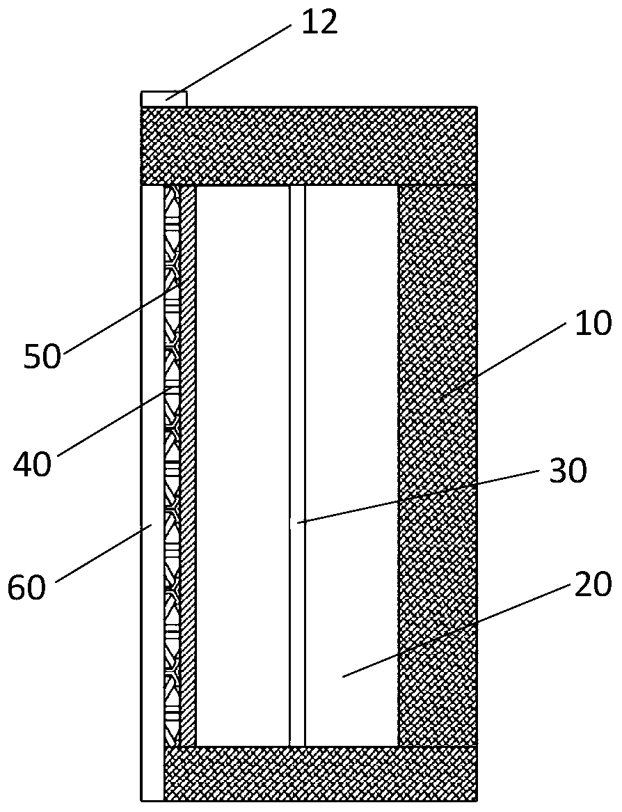
[0038] The heat storage type electric heater provided by the present invention can be used in various types of existing heat storage type electric heaters, and the isothermal heat release of the heat storage type electric heater is realized through the phase change layer, figure 1 , figure 2 shows a th...
PUM
| Property | Measurement | Unit |
|---|---|---|
| Phase transition temperature | aaaaa | aaaaa |
Abstract
Description
Claims
Application Information