Individual thermal comfort control system and method based on computer vision monitoring

A computer vision and control system technology, applied in the field of HVAC, can solve problems such as inability to meet thermal comfort

Active Publication Date: 2021-04-09
XI'AN UNIVERSITY OF ARCHITECTURE AND TECHNOLOGY
View PDF3 Cites 11 Cited by
  • Summary
  • Abstract
  • Description
  • Claims
  • Application Information

AI Technical Summary

Problems solved by technology

[0009] The purpose of the present invention is to provide an individual thermal comfort control system and control method based on computer vision monitoring, which solves the problem that the prior art cannot satisfy thermal comfort

Method used


Image

  • Individual thermal comfort control system and method based on computer vision monitoring
  • Individual thermal comfort control system and method based on computer vision monitoring
  • Individual thermal comfort control system and method based on computer vision monitoring

Examples


Embodiment Construction

[0057] The present invention will be further described in detail below in conjunction with specific embodiments, which are explanations of the present invention rather than limitations.

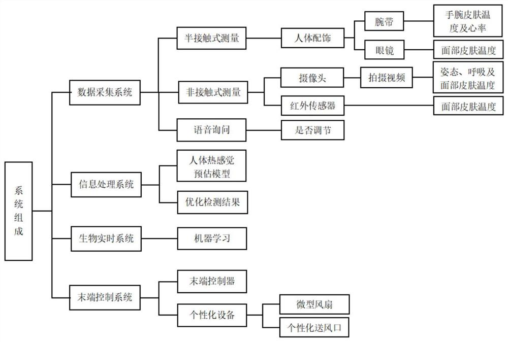
[0058] like figure 1 As shown, the present invention discloses an individual thermal comfort control system based on computer vision monitoring, including a data acquisition system, an information processing system, a biological real-time system, an intelligent voice inquiry module, an information processing system, and a terminal control system; the data acquisition system includes A semi-contact measuring unit and a non-contact measuring unit, the semi-contact measuring unit is arranged on the human body, the non-contact measuring unit includes an infrared sensor 5 and a camera 4 with a temperature measurement function; the camera 4 is used to collect video information, and the infrared sensor 5 is used to collect body temperature information; the information processing system includes a st...


PUM


Abstract

The invention belongs to the technical field of heating and ventilation, and discloses an individual thermal comfort control system and control method based on computer vision monitoring. The control system comprises a data acquisition system, an information processing system, an intelligent voice inquiry module, a tail end control system and a biological real-time system; the data acquisition system comprises a semi-contact measurement unit and a non-contact measurement unit; the non-contact measurement unit comprises an infrared sensor and a camera; a skeleton node identification module and an Euler video amplification module are arranged in the camera; the information processing system comprises a storage module, a human body thermal sensation estimation module and a comparison module; the human body thermal sensation estimation module is used for obtaining a predicted thermal sensation value; the comparison module is connected with the intelligent voice inquiry module; the tail end control system comprises a tail end controller, and the tail end controller is connected with external equipment; and the data acquisition system and the human body thermal sensation estimation module are connected with the biological real-time system. The problem that thermal comfort cannot be met in the prior art is solved.

Description

technical field [0001] The invention relates to the field of HVAC technology, in particular to an individual thermal comfort control system and control method based on computer vision monitoring. Background technique [0002] A comfortable office working environment is the prerequisite for efficient office work. Currently, HVAC systems widely used in office buildings consume a lot of energy, but they do not meet the thermal comfort level required by personnel. Among the currently commonly used HVAC systems, such as the split-type air-conditioning system, it is impossible to accurately measure real-time human body temperature and thermal comfort information, and it is usually only adjusted when the human body is in an uncomfortable state. Therefore, there are problems of deviation and hysteresis in the adjustment of this system, and the set point adjusted by the occupants according to their own perception cannot meet the high-efficiency human thermal comfort and is not conduc...

Claims


Application Information

Patent Timeline
Patent Type & Authority Applications(China)
IPC IPC(8): G05B15/02G05B19/418G01J5/00
CPCG05B15/02G05B19/418G01J5/0025G05B2219/2642G05B19/042G05B2219/2614Y02B30/70Y02P90/02
Inventor 杨斌姚黄成郭钰耀金大程成孝刚陈梦伟李安桂
Owner XI'AN UNIVERSITY OF ARCHITECTURE AND TECHNOLOGY
Why Eureka
Try Eureka