Stable tube pillow of electric force tube

A power pipe and pipe pillow technology, which is applied in the field of power pipe and pipe pillows, can solve the problems of general connection stability of pipe pillows, and achieve the effects of reducing the burden of wedges, stable connection and good reinforcement.

Active Publication Date: 2019-06-21
GUANGXI POWER GRID CO LTD NANNING POWER SUPPLY BUREAU
View PDF9 Cites 0 Cited by
  • Summary
  • Abstract
  • Description
  • Claims
  • Application Information

AI Technical Summary

Problems solved by technology

[0004] The current connection stability of pipe pillows is average, and those skilled in the art hope to develop a pipe pillow with better connection stability

Method used


Image

  • Stable tube pillow of electric force tube
  • Stable tube pillow of electric force tube
  • Stable tube pillow of electric force tube

Examples


Embodiment 1

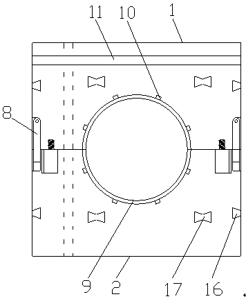
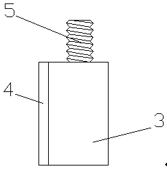
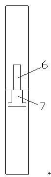
[0049] Such as Figure 1-5 As shown, a stable power tube pillow includes an upper pillow 1 and a lower pillow 2, and the upper pillow 1 and the lower pillow 2 are provided with semicircular grooves (not shown), the The upper pillow 1 is provided with an insertion body for pre-fixation, and the lower pillow 2 is provided with an insertion groove matched with the insertion body, and the insertion body includes an insertion strip 3, a magnet block 4 and a threaded rod 5, The insert bar 3 and the threaded rod 5 are integrally arranged, the magnet block 4 is located on one side of the insert bar 3, the magnet block 4 is fixedly connected with the insert bar 3, and the upper pillow 1 is provided with threaded Screw holes (not shown) that match the rods 5, the upper pillow 1 and the insertion bar 3 are detachably connected through the threaded rod 5 and the screw holes, and the upper pillow 1 and the lower pillow 2 are respectively provided with the first A storage slot 6 and a seco...

Embodiment 2

[0060] Such as Figure 1-5 As shown, a stable power tube pillow includes an upper pillow 1 and a lower pillow 2, and the upper pillow 1 and the lower pillow 2 are provided with semicircular grooves (not shown), the The upper pillow 1 is provided with an insertion body for pre-fixation, and the lower pillow 2 is provided with an insertion groove matched with the insertion body, and the insertion body includes an insertion strip 3, a magnet block 4 and a threaded rod 5, The insert bar 3 and the threaded rod 5 are integrally arranged, the magnet block 4 is located on one side of the insert bar 3, the magnet block 4 is fixedly connected with the insert bar 3, and the upper pillow 1 is provided with threaded Screw holes (not shown) that match the rods 5, the upper pillow 1 and the insertion bar 3 are detachably connected through the threaded rod 5 and the screw holes, and the upper pillow 1 and the lower pillow 2 are respectively provided with the first A storage slot 6 and a seco...


PUM


Abstract

The present invention discloses a stable tube pillow of an electric force tube. The tube pillow comprises an upper pillow part and a lower pillow part, the upper pillow part and the lower pillow partare both provided with semicircular grooves, the upper pillow part is provided with an insertion body for pre-fixing, the lower pillow part is provided with an insertion groove paired with the insertion body, the insertion body comprises an insertion strip, a magnet block and a threaded rod, the insertion strip and the threaded rod are integrally arranged, the magnet block is located at one side of the insertion strip, the magnet block is fixedly connected with the insertion strip, the upper pillow part is provided with a screw hole paired with the threaded rod, the upper pillow part and the insertion strip are detachably connected through the threaded rod and the screw hole, the upper pillow part and the lower pillow part are respectively provided with a first receiving groove and a second receiving groove, and the two sides of the upper pillow part are both provided with metal connection parts paired with the first receiving groove and the second receiving groove. The stable tube pillow of the electric force tube is good in connection stability.

Description

technical field [0001] The invention relates to a stable power pipe pillow. Background technique [0002] The pipe pillow provides guarantee for the quality of the cable and cable pipe buried project, and provides convenience for the cable and cable pipe buried construction. Moreover, the pipe pillow product is standardized, the cable and cable pipe buried engineering technology is improved, and the production pipe is saved. The material of the pillow product and the labor to punch the steel bar hole on the pipe sleeper. [0003] The current pipe pillow is composed of the pipe pillow corner, the pipe pillow edge, the pipe pillow plate, the pipe pillow rib, the inner edge of the single pipe pillow, the pin, the pin hole, the cable pipe hole edge, and the cable pipe hole, and is divided into The upper and lower joints are assembled by inserting pins into the pin holes. [0004] The current connection stability of pipe pillows is average, and those skilled in the art hope to ...

Claims


Application Information

Patent Timeline
Patent Type & Authority Applications(China)
IPC IPC(8): H02G9/06C08L61/06C08L9/02C08K13/04C08K7/08C08K5/098C08K3/26C08K5/42C08J9/08
Inventor 不公告发明人
Owner GUANGXI POWER GRID CO LTD NANNING POWER SUPPLY BUREAU
Why Eureka
Try Eureka