
A bias voltage output circuit and a driving circuit

A technology of bias voltage and output circuit, applied in the field of communication, can solve the problems of plosive sound, ESD and EOS problems of external audio output devices at the same time

Active Publication Date: 2019-06-21
HUAWEI DEVICE CO LTD
View PDF15 Cites 4 Cited by
  • Summary
  • Abstract
  • Description
  • Claims
  • Application Information

AI Technical Summary

Problems solved by technology

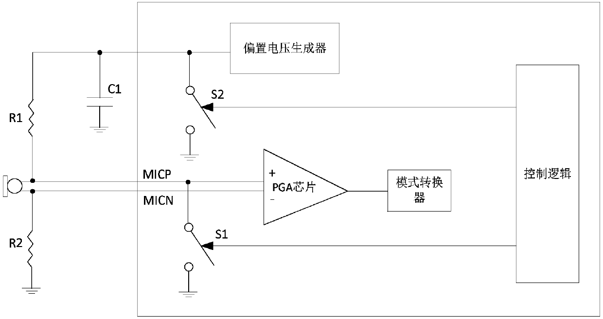
However, since the switch S1 directly contacts the headphone jack, the ESD can be directly hit on the switch S1 through the MICP, which will cause ESD and EOS problems of the MICBIAS chip
[0007] It can be seen that the problems of plosive sound, ESD and EOS during the plugging and unplugging process of the external audio output device cannot be solved simultaneously in the prior art

Method used


Image

  • A bias voltage output circuit and a driving circuit
  • A bias voltage output circuit and a driving circuit
  • A bias voltage output circuit and a driving circuit

Examples


Embodiment Construction

[0060] In order to make the purpose, technical solutions and advantages of the embodiments of the present application more clear, the embodiments of the present invention will be further described in detail below in conjunction with the accompanying drawings.

[0061] In the following, some terms used in the embodiments of the present application are explained, so as to facilitate the understanding of those skilled in the art.

[0062](1) Plosive sound: refers to the transient audio signal generated on an external audio playback device when using an external audio playback device, such as earphones or speakers, to play sound. This kind of plosive sound is mainly caused by the jump of the DC level on the playback device connected to the external audio playback device, and generally exists in the following two application scenarios: the normal (or chip) of the playback device system (or Abnormal) during the power-on and power-off process, and during the connection (or disconnect...


PUM


Abstract

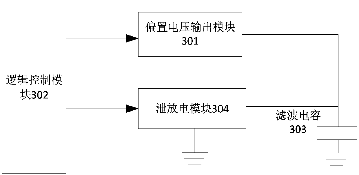
The invention provides a bias voltage output circuit and a driving circuit. The bias voltage output circuit comprises a bias voltage output module used for outputting bias voltage under the action ofa logic control module, and the bias voltage is used for driving an audio output device; a filter capacitor which is used for filtering noise generated by the bias voltage output module in the bias voltage output process and storing electric quantity in the bias voltage output process of the bias voltage output module; a discharging module which is used for discharging the electric quantity storedby the filter capacitor under the action of the logic control module; a logic control module which is used for outputting audio signals to an audio output device when determining that the audio output device accesses audio playing equipment, triggering the bias voltage output module to output the bias voltage, controlling the discharge module to forbid discharging the electric quantity stored bythe filter capacitor, triggering the bias voltage output module to stop outputting the bias voltage when determining that the audio output device is disconnected with the audio playing equipment, andcontrolling the discharge module to discharge the electric quantity stored by the filter capacitor.

Description

[0001] This application claims the priority of the Chinese patent application with the application number 201711329076.9 and the application name "A method and device for interface display" submitted to the China Patent Office on December 13, 2017, the entire contents of which are incorporated in this application by reference . technical field [0002] The present application relates to the field of communication technology, and in particular to a bias voltage output circuit and a driving circuit. Background technique [0003] In the process of rapid development, terminal equipment presents more and more functions. It has become a part of daily life for a user to use a terminal device to play an audio file or a video file. For example, a user can play an audio file and listen to it by plugging a headset into the headset jack of the terminal device. [0004] When the earphone is plugged and unplugged, the DC level of the terminal device will jump, thereby generating pop noi...

Claims


Application Information

Patent Timeline
Patent Type & Authority Applications(China)
IPC IPC(8): H04R1/10H04R3/00
Inventor 张洵李勇舒迎飞王浩
Owner HUAWEI DEVICE CO LTD
Learn More