Lead-resistance-removed resistance signal source and resistance measuring circuit thereof
A resistance signal source, lead resistance technology, applied in the measurement of electrical variables, measurement of resistance/reactance/impedance, measurement devices, etc., can solve the problems of complicated wiring, long sampling time, etc., to simplify software design, wiring is simple and convenient, shortening Effect of sampling period
- Summary
- Abstract
- Description
- Claims
- Application Information
AI Technical Summary
Problems solved by technology
Method used
Image
Examples
Embodiment 1
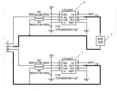
[0041] Such as figure 1 As shown, it is a schematic diagram of a resistance signal source for eliminating lead resistance in this embodiment, which includes a standard resistor 1 , a first voltage-controlled voltage source 2 and a second voltage-controlled voltage source 3 . The two ends of the standard resistor are respectively connected to the first connection line 4 and the second connection line 5, and the two free ports of the two connection lines are the first interface A and the second interface B respectively; the inverting input terminal of the first voltage-controlled voltage source 2 It is the third interface, the non-inverting input end is connected to the free end of the first connecting line 4, and the output end is connected to the other end of the first connecting line 4; the inverting input end of the second voltage-controlled voltage source 3 is the fourth interface, The non-inverting input end is connected to the free end of the second connection line 5 , an...
Embodiment 2
[0043] Such as figure 2As shown, it is a schematic diagram of the resistance signal source of this embodiment, which is different from Embodiment 1 in that the positive phase input terminal of the first voltage-controlled voltage source 2 is connected to the free end of the first connecting line 4, and the output terminal is connected to One end of the second connection line 5 connected to the standard resistance 1, the positive phase input terminal of the second voltage-controlled voltage source 3 is connected to the free end of the second connection line 5, and the output end is connected to the second connection line 5 and the standard resistance 1 The connected end is the same as that of Embodiment 1, and will not be repeated here.
[0044] Such as image 3 Shown is the circuit diagram of the resistance signal source of this embodiment. In this embodiment, the first voltage-controlled voltage source 2 includes a first high-precision instrument amplifier 4 and its periphe...
Embodiment 3
[0046] Such as Figure 4 As shown, it is a schematic diagram of the resistance signal source of this embodiment, which is different from Embodiment 1 in that the non-inverting input terminal is connected to the free end of the first connecting line 4, and the output terminal is connected to the other end of the first connecting line , the non-inverting input end of the second voltage-controlled voltage source 3 is connected to the free end of the second connection line 5, and the output end is connected to one end of the first connection line 5 connected to the standard resistor 1, and the others are the same as in Embodiment 1, here No longer.
[0047] The resistance measurement circuit of the resistance signal source for lead resistance elimination provided by the present invention includes the resistance signal source and the measurement device described in the above embodiments, and all interfaces of the resistance signal source are respectively connected to the measuremen...
PUM
 Abstract
Description
Claims
Application Information
 - R&D
- Intellectual Property
- Life Sciences
- Materials
- Tech Scout
- Unparalleled Data Quality
- Higher Quality Content
- 60% Fewer Hallucinations
Browse by: Latest US Patents, China's latest patents, Technical Efficacy Thesaurus, Application Domain, Technology Topic, Popular Technical Reports.
© 2025 PatSnap. All rights reserved.Legal|Privacy policy|Modern Slavery Act Transparency Statement|Sitemap|About US| Contact US: help@patsnap.com


