Portable line fault monitoring/analyzing recorder

A line fault and recorder technology, which is applied in the field of analysis recorder, can solve the problems of low probability of manual successful detection of fault points, inability to fully meet the needs of fault diagnosis, poor contact of contactor contacts, etc., to achieve the purpose of recording voltage and current curves The effect of long time, easy connection of fault detection points, and short curve sampling period

Inactive Publication Date: 2014-12-24
唐山三友集团兴达化纤有限公司
View PDF11 Cites 1 Cited by
  • Summary
  • Abstract
  • Description
  • Claims
  • Application Information

AI Technical Summary

Problems solved by technology

[0003] When there is a short-term fault in the automatic control system circuit or device of continuous production, such as poor contact of the contactor (the resistance of the circuit becomes larger), the resistance of the second action of the contactor is normal, etc., without stopping the machine, the traditional Most of the line fault detection methods are manual monitoring of line voltage and current through multimeters, clamp meters, oscilloscopes, etc., and the probability of manual successful detection of fault points is extremely low
For example, by laying detection lines and connecting the detection points to the distributed control system to generate current and voltage curves, this method requires parking to connect the detection points, which is time-consuming and laborious to operate, and the sampling period of the current and voltage generated by the distributed control system is relatively long (500 milliseconds-1 seconds), which cannot fully meet the needs of fault diagnosis

Method used


Image

  • Portable line fault monitoring/analyzing recorder
  • Portable line fault monitoring/analyzing recorder

Examples


Embodiment Construction

[0015] The present invention will be further described below in conjunction with the accompanying drawings.

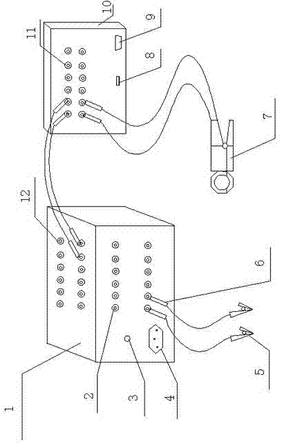
[0016] The invention is a portable line fault monitoring and analyzing recorder, which consists of a paperless recorder 10, a voltage conversion device 1, a clamp current transformer 7, connecting wires and the like. See the specific structure figure 1 , figure 2 .

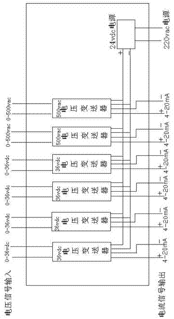
[0017] See figure 1 , there are six signal input channels on the side of the voltage conversion device 1, and the input channels are respectively provided with input channel banana sockets 2. In this embodiment, each input channel is provided with a pair of input channel banana sockets 2, and the pair is two , including four DC voltage input channels between 0-36 volts, and two AC voltage input channels between 0-500 volts. There are six output channels corresponding to the input channels, and the six output channels are arranged on the voltage conversion device 1 . The output channels are provided w...


PUM


Abstract

The invention provides a portable line fault monitoring/analyzing recorder. The portable line fault monitoring/analyzing recorder comprises a voltage type signal acquisition device, a paperless recorder, a voltage converter and a current transformer; the voltage type signal acquisition device is connected with the voltage converter, the voltage converter is connected with the paperless recorder by use of a wire, and the paperless recorder is connected with the current transformer; a signal acquired by the voltage type signal acquisition device is sent to the voltage converter and converted into a DC signal by the voltage converter, and the DC signal is sent to the paperless recorder; a current signal is detected by use of the current transformer of a split core type, and the split core type current transformer outputs a DC signal which directly goes into the paperless recorder; the paperless recorder records voltage and current signal curves. The portable line fault monitoring/analyzing recorder has the advantages of easy fault detection point connection, diversified detection ways, long voltage and current curve recording time and short curve sampling period, and further is capable of quickly realizing monitoring on a continuous-production automatic system out of order temporarily and analyzing the part out of order of a detected device by use of the curves recorded by the paperless recorder. The portable line fault monitoring/analyzing recorder is simple to operate and convenient to carry and use.

Description

technical field [0001] The invention relates to an analysis recorder in the measurement field, in particular to a [0002] A portable line fault monitoring and analysis recorder. Background technique [0003] When there is a short-term fault in the automatic control system circuit or device of continuous production, such as poor contact of the contactor (the resistance of the circuit becomes larger), the resistance of the second action of the contactor is normal, etc., without stopping the machine, the traditional Most of the line fault detection methods are to monitor the line voltage and current manually through multimeters, clamp meters, oscilloscopes, etc., and the probability of successfully detecting the fault point is extremely low. For example, by laying detection lines and connecting the detection points to the distributed control system to generate current and voltage curves, this method requires parking to connect the detection points, which is time-consuming and...

Claims


Application Information

Patent Timeline
Patent Type & Authority Applications(China)
IPC IPC(8): G01R31/08
Inventor 彭宴星张志军曹建志王太双刘桂红郭建斌陈太宝班耐新杨守琳张荣成林紫丽庞松美
Owner 唐山三友集团兴达化纤有限公司
Why Eureka
Try Eureka