Radar sensor for motor vehicles

一种雷达传感器、机动车的技术,应用在用于机动车的雷达传感器领域,能够解决相位变化过程取决载波频率、距离和速度、不可能、速度估计妨碍等问题

Active Publication Date: 2019-06-21
ROBERT BOSCH GMBH
View PDF13 Cites 4 Cited by
  • Summary
  • Abstract
  • Description
  • Claims
  • Application Information

AI Technical Summary

Problems solved by technology

Here too, the following problem arises: the course of the phase change over slow time depends on the carrier frequency, distance and speed, and a change in the carrier frequency leads to a non-linear change in the phase
As a result, velocity estimation (for example by means of Fourier analysis processing) is hampered or not possible at all

Method used


Image

  • Radar sensor for motor vehicles
  • Radar sensor for motor vehicles
  • Radar sensor for motor vehicles

Examples


Embodiment Construction

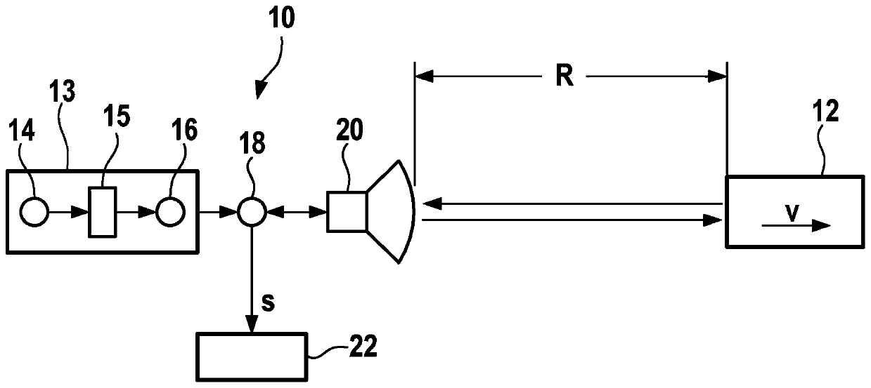
[0033] exist figure 1 In the drawing, an FMCW radar sensor 10 is shown as a simplified block diagram, which is installed at the front, for example in a motor vehicle, and which is used to measure the distance R and the relative velocity v of an object 12 , for example a vehicle driving ahead. The radar sensor 10 has a signal generator 13 with an oscillator 14, a modulator 15 and a mixer 16 which mixes the wave train generated by the modulator to a high frequency by up-mixing with the corresponding carrier frequency. in the frequency band and thus generate the radar signal to be transmitted. Alternatively, the signal generation can take place directly from the wave train by means of an oscillator. The radar signal is then supplied via a transmitting and receiving mixer 18 to a transmitting and receiving device 20 from which the signal is emitted towards the object 12 . The signal reflected on the object is received by the transmitting and receiving device 20 and mixed with a ...


PUM


Abstract

The invention relates to a radar sensor for motor vehicles, comprising a signal generator, which is configured so as to generate a radar signal containing a cyclically repeating sequence of N wave trains Wj, j = 1, N, which can be successively sent at time intervals T'c,j and occupy respective frequency bands that differ from each other in terms of the centre frequencies fc,j thereof, characterised in that, for the time intervals Tc,j and the centre frequencies fc,j, the relation T'c,j* fc,j = X with a constant parameter X holds good.

Description

technical field [0001] The invention relates to a radar sensor for a motor vehicle having a signal generator which is configured to generate a radar signal comprising N wave trains (Wellenzug) W j , a periodically repeated sequence of j=1,...,N, the N wave trains are successively separated by a time interval T' c,j transmit and occupy the corresponding frequency band at its intermediate frequency f c,j different aspects. Background technique [0002] Radar systems for measuring distances, relative speeds and angles of objects such as vehicles and obstacles are increasingly being used in motor vehicles for safety and comfort functions. The accuracy of radar measurements in terms of distance, speed and angle plays an increasingly important role here, since driver assistance systems and automated driving functions require the most accurate possible detection of the surrounding environment. [0003] Furthermore, the separation capability of the radar sensor in terms of all th...

Claims


Application Information

Patent Timeline
Patent Type & Authority Applications(China)
IPC IPC(8): G01S13/34G01S13/93G01S7/35G01S7/02G01S13/931
CPCG01S7/023G01S13/343G01S13/347G01S13/931G01S7/356G01S7/0232G01S7/0234
Inventor G·哈科拜杨K·A·D·阿尔马尼奥斯M·朔尔
Owner ROBERT BOSCH GMBH
Why Eureka
Try Eureka