Novel rapid sputum suction device

A sputum suction device, fast technology, applied in the direction of suction equipment, etc., can solve the problems of environmental pollution, waste of medical resources, inability to treat sputum, etc., and achieve the effect of reducing garbage pollution

Inactive Publication Date: 2019-06-25
江苏华飞医疗科技有限公司
View PDF0 Cites 1 Cited by
  • Summary
  • Abstract
  • Description
  • Claims
  • Application Information

AI Technical Summary

Problems solved by technology

[0002] There are many patients with respiratory diseases in the hospital. Such patients need to suck sputum. Some patients with respiratory medical diseases will have excessive sputum. If they are not treated in time, it will threaten the life and health of patients. Many sputum suction devices When in use, the sucked sputum cannot be processed, and the entire sputum suction device needs to be discarded, which causes a certain degree of waste of medical resources, is not very environmentally friendly, and causes environmental pollution.

Method used


Image

  • Novel rapid sputum suction device
  • Novel rapid sputum suction device

Examples


Embodiment 1

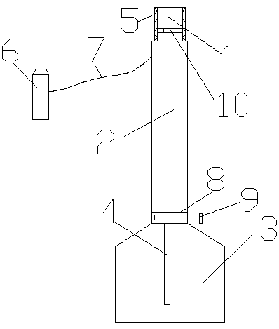
[0013] A new type of rapid sputum suction device, which is provided with a sputum suction head 1, a guide tube 2 is arranged on the back side of the sputum suction head 1, a sputum suction chamber 3 is arranged on the guide tube 2, and a sputum suction chamber 3 is arranged on the guide tube 2. A partition 4 is arranged inside, a connecting hole is arranged on the partition 4 , a rubber layer 5 is arranged on the suction head 1 , and a plug 6 is arranged beside the suction head 1 .

[0014] A traction belt 7 is arranged between the plug 6 and the suction head 1, and the traction belt 7 is a rubber belt.

[0015] A connection device 8 is provided between the sputum suction chamber 3 and the guide tube 2 .

[0016] The connecting device 8 is a connecting cavity, and a locking rod 9 is arranged outside the connecting cavity.

Embodiment 2

[0018] A new type of rapid sputum suction device, which is provided with a sputum suction head 1, a guide tube 2 is arranged on the back side of the sputum suction head 1, a sputum suction chamber 3 is arranged on the guide tube 2, and a sputum suction chamber 3 is arranged on the guide tube 2. A partition 4 is arranged inside, a connecting hole is arranged on the partition 4 , a rubber layer 5 is arranged on the suction head 1 , and a plug 6 is arranged beside the suction head 1 .

[0019] A traction belt 7 is arranged between the plug 6 and the suction head 1, and the traction belt 7 is a rubber belt.

[0020] A connection device 8 is provided between the sputum suction chamber 3 and the guide tube 2 .

[0021] The connecting device 8 is a connecting cavity, and a locking rod 9 is arranged outside the connecting cavity.

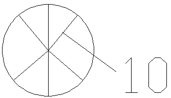
[0022] The inner side of the sputum suction head 1 is provided with a shunt net 10, and the shunt net 10 has a hexagonal structure.


PUM


Abstract

A novel rapid sputum suction device is provided with a sputum suction head; a guide tube is arranged at the back side of the sputum suction head, a sputum suction chamber is arranged on the guide tube, a partition board is arranged in the sputum suction chamber, a connecting hole is arranged on the partition board, a rubber layer is arranged on the sputum suction head, and an end cap is arranged beside the sputum suction head. The sputum suction head is arranged on the sputum suction device, so sputum can be quickly sucked, and the timely suction of sputum from patients is facilitated; the partition board is arranged in the sputum suction chamber, the sputum can be allowed to flow, and the accumulation of the sputum in the sputum suction chamber is avoided; a connecting device is arrangedbetween the sputum suction chamber and the guide tube, so the sputum suction chamber can be dismantled, the re-use of the sputum suction device is facilitated, and the garbage pollution of medical devices is reduced.

Description

technical field [0001] The invention relates to a sputum suction device, in particular to a novel fast sputum suction device. Background technique [0002] There are many patients with respiratory diseases in the hospital. Such patients need to suck sputum. Some patients with respiratory medical diseases will have excessive sputum. If they are not treated in time, it will threaten the life and health of patients. Many sputum suction devices When in use, the suctioned sputum cannot be processed, and the entire sputum suction device needs to be discarded, which causes a certain degree of waste of medical resources, is not very environmentally friendly, and causes environmental pollution. Contents of the invention [0003] The purpose of the present invention is to provide a novel fast sputum suction device which is reasonable in structure and convenient for reuse. [0004] The technical solution of the present invention is: a new type of rapid sputum suction device, which i...

Claims


Application Information

Patent Timeline
Patent Type & Authority Applications(China)
IPC IPC(8): A61M1/00
Inventor 陈兵
Owner 江苏华飞医疗科技有限公司
Why Eureka
Try Eureka