
Fault display method and fault display system of bridge monitoring system

A fault display and monitoring system technology, which is applied in the direction of instruments, etc., can solve the problems of increasing bridge operating costs, low sensor life, and prone to faults, etc., and achieve the effect of low layout cost, good visualization effect, and reliable and stable operation

Pending Publication Date: 2019-06-25
王涛 +6
View PDF6 Cites 4 Cited by
  • Summary
  • Abstract
  • Description
  • Claims
  • Application Information

AI Technical Summary

Problems solved by technology

Although a variety of sensors are installed on the existing bridges to accurately grasp the overall state of the bridge, because the bridge sensors are all installed on the bridge body, and some are even exposed, this leads to a low service life of the sensors and is prone to failure , in the prior art, the computer in the central control room sends out a fault signal, and then checks it out. However, on some bridges that have been built for a long time, it is necessary to install a variety of sensors later, and to set up the central control room independently. Relevant monitoring computer, this is a relatively large renovation investment for bridges that have been built for a long time, and it is also necessary to hire special staff in the monitoring room, which virtually increases the operating cost of the bridge

Method used


Image

  • Fault display method and fault display system of bridge monitoring system
  • Fault display method and fault display system of bridge monitoring system

Examples


Embodiment Construction

[0025] The following will clearly and completely describe the technical solutions in the embodiments of the present invention with reference to the accompanying drawings in the embodiments of the present invention. Obviously, the described embodiments are only some, not all, embodiments of the present invention. Based on the embodiments of the present invention, all other embodiments obtained by persons of ordinary skill in the art without creative efforts fall within the protection scope of the present invention.

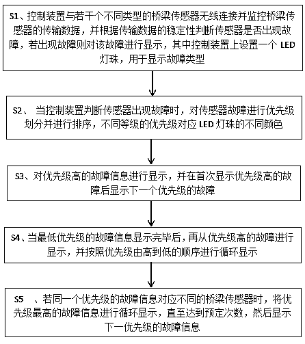
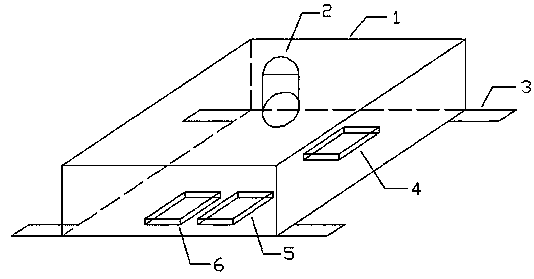
[0026] see Figure 1-2 , the fault display method of the bridge monitoring system proposed in the present invention is mainly aimed at displaying whether various sensors of the bridge monitoring system have faults. The bridge sensors in the prior art will send a fault signal to the central control room when a fault occurs, but this technology is only applicable to newly built bridges. For existing old bridges that have been built for a long time, there is no space,...


PUM


Abstract

The invention relates to a fault display method and a fault display system of a bridge monitoring system. According to the fault display method, faults of common sensors of a bridge are represented through different colors and different flickering modes of the LED lamp beads, wherein different colors of the LED lamp beads represent that sensors with different priorities fail; each flickering moderepresents that one specific sensor breaks down. Meanwhile, the invention provides a display system based on the fault display method, the display system only needs to be provided with one main control board and one LED lamp bead, so the whole system is extremely simple in structure, low in cost and good in reliability.

Description

technical field [0001] The invention relates to the technical field of bridges, in particular to a fault display method and a fault display system of a bridge monitoring system. Background technique [0002] In the prior art, in order to ensure the smooth operation of all aspects of the bridge, various types of sensors are usually installed on the bridge, and various types of sensors are wirelessly connected to the monitoring system, such as load sensors and pressure sensors. Although a variety of sensors are installed on the existing bridges to accurately grasp the overall state of the bridge, because the bridge sensors are all installed on the bridge body, and some are even exposed, this leads to a low service life of the sensors and is prone to failure , in the prior art, the computer in the central control room sends out a fault signal, and then checks it out. However, on some bridges that have been built for a long time, it is necessary to install a variety of sensors l...

Claims


Application Information

Patent Timeline
Patent Type & Authority Applications(China)
IPC IPC(8): G01D18/00
Inventor 唐明星赵长博魏君鹏周晓英徐勇赵向阳李素梅李雪荣丁西焘李文超曹莉张冬
Owner 王涛
Learn More