An industrial wireless sensor network clock frequency offset estimation method based on timing response

A wireless sensor network and clock frequency technology, applied in wireless communication, power management, transmission system, etc., can solve the problems of large synchronization overhead, achieve low power consumption requirements, save energy, and improve security

Active Publication Date: 2019-06-25
CHONGQING UNIV OF POSTS & TELECOMM
View PDF4 Cites 21 Cited by
  • Summary
  • Abstract
  • Description
  • Claims
  • Application Information

AI Technical Summary

Problems solved by technology

Existing clock frequency offset estimation methods generally require special synchronization messages, and need to exchange time stamp information during transmission, resulting in large synchronization overhead

Method used


Image

  • An industrial wireless sensor network clock frequency offset estimation method based on timing response
  • An industrial wireless sensor network clock frequency offset estimation method based on timing response
  • An industrial wireless sensor network clock frequency offset estimation method based on timing response

Examples


Embodiment

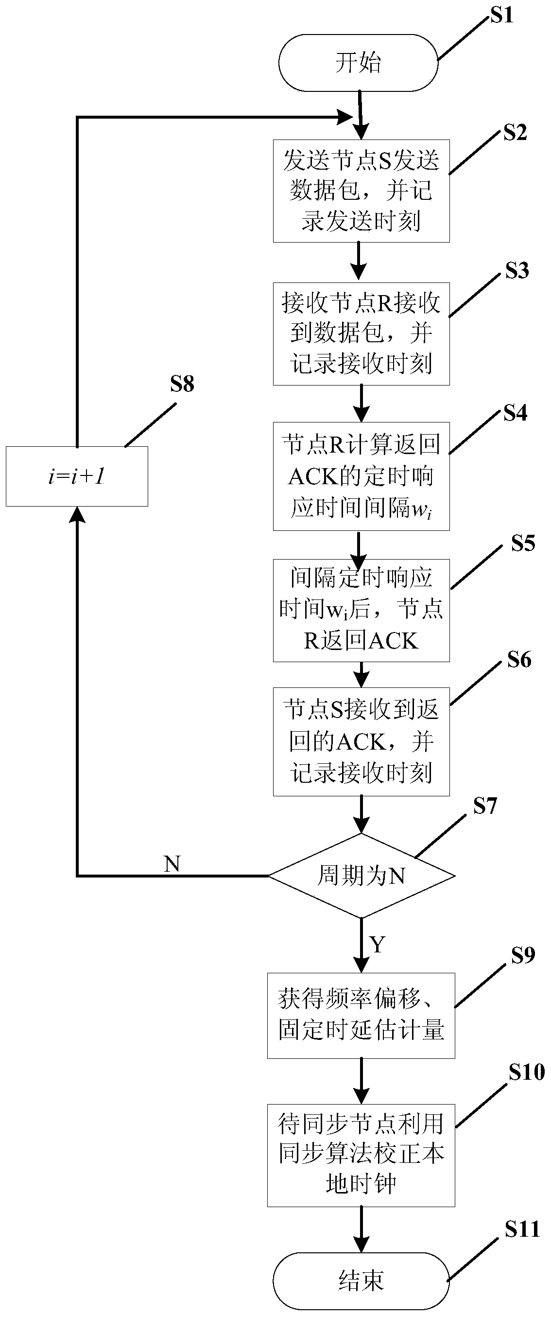
[0074] figure 2 It is a flowchart of the clock frequency offset estimation method based on timing response according to the present invention, such as figure 2 As shown, the clock frequency offset estimation method specifically includes the following steps:

[0075] S1: The synchronization process starts.

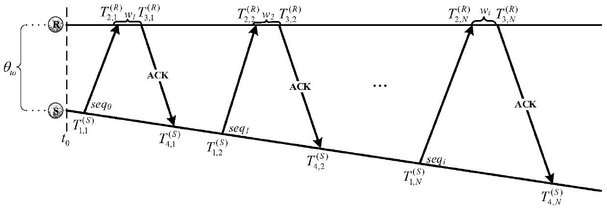
[0076] S2: The sending node S sends a data packet with the sequence number Seq to the receiving node R, and records the sending time

[0077] S3: The receiving node R receives the data packet and records the receiving time

[0078] S4: The receiving node R uses the calculation rule Seq%i according to the sequence number of the received data packet to obtain the timing response time interval w that needs to wait for the feedback ACK i .

[0079] S5: receiving node R interval w i Respond to ACK after time, and record the corresponding sending time

[0080] S6: Node S receives the response ACK message from node R, and records the corresponding receiving time

...


PUM


Abstract

The invention relates to an industrial wireless sensor network clock frequency offset estimation method based on timing response, and belongs to the technical field of wireless sensor networks. In themethod, the node to be synchronized sends a data packet to the reference node; the reference node receives the data packet; a corresponding timing response time is mapped according to the serial number of the data packet, a confirmation message is replied after the time interval, time stamp information does not need to be exchanged between the to-be-synchronized node and the reference node, and after multiple times of communication interaction, the to-be-synchronized node can estimate relative frequency offset and fixed time delay between node clocks. The method is easy to integrate into an industrial wireless sensor network with a time slot mechanism, a message special for time synchronization parameter estimation does not need to be sent and received independently, long-term tracking ofclock frequency offset can be achieved only with low calculation cost, communication expenditure is reduced, and energy consumption is reduced; Meanwhile, time stamps do not need to be interacted among the nodes, so that the safety of time synchronization parameter estimation is improved.

Description

technical field [0001] The invention belongs to the technical field of wireless sensor networks, and relates to a method for estimating frequency offsets of timing response clocks suitable for industrial wireless sensor networks. Background technique [0002] The wireless sensor network consists of many sensor nodes that are spatially distributed, cheap, and tiny, and its computing, storage, and energy are all limited, and each node runs on its own independent clock. Due to the characteristics of flexible deployment and low cost, wireless sensor networks have been widely used in many fields, such as industrial fields. Traditional industrial networks mostly use wired connections, which limit their deployment flexibility and intelligent control of industrial processes. It is based on the advantages of wireless sensor network that industrial wireless sensor network came into being. Wireless micro sensor nodes are installed on many devices in the industrial field, responsible f...

Claims


Application Information

Patent Timeline
Patent Type & Authority Applications(China)
IPC IPC(8): H04L27/00H04J3/06H04L1/16H04W52/02H04W56/00
CPCH04W52/02H04W56/00H04L27/00H04J3/0667H04J3/06H04L1/16H04L5/0055
Inventor 王恒钟杨余斐
Owner CHONGQING UNIV OF POSTS & TELECOMM
Why Eureka
Try Eureka