Method for detecting cutter tooth flank surface wear characteristics of high-feed milling cutter

A technology of wear characteristics and detection methods, applied in the direction of measuring/indicating equipment, metal processing machinery parts, metal processing equipment, etc., can solve the problem of inability to fully reveal the wear characteristics of the cutter tooth flank and the experimental data of the cutter tooth flank wear Errors, high cutting edge stress, etc.

Active Publication Date: 2019-06-28
HARBIN UNIV OF SCI & TECH
View PDF11 Cites 11 Cited by
  • Summary
  • Abstract
  • Description
  • Claims
  • Application Information

AI Technical Summary

Problems solved by technology

When using this type of milling cutter to process large titanium alloy structural parts, due to the influence of cutter tooth error distribution and milling vibration, problems such as excessive cutting edge stress and fast wear of the cutter teeth are prominent
[0003] The existing high-feed milling cutter tooth wear test method adopts the method of stopping the machine to measure the tool wear, ignoring the influence of the dissipation of the thermal coupling field of the milling cutter on the accuracy of the wear test data of the cutter tooth flank, and the milling cutter caused by tool change. The influence of mode change on milling vibration introduces irrelevant variables that affect the wear process of milling cutter teeth, which makes the experimental data of cutter tooth flank wear have large errors; the existing measurement of milling cutter tooth flank wear is concentrated In the measurement of the wear width of a specific area, it cannot completely reflect the structural changes in the shape of the entire cutting edge and the flank of the cutter tooth, and it is difficult to identify the wear characteristics of the flank face of the cutter tooth; The analysis method of the flank wear characteristics ignores the influence of the cutter tooth error distribution and milling vibration on the flank wear characteristics of the cutter teeth, and does not fully reveal the cause of the flank wear of the cutter teeth
Therefore, the detection method for the flank wear characteristics of this type of milling cutter cannot fully reveal the flank wear characteristics of the cutter teeth.

Method used


Image

  • Method for detecting cutter tooth flank surface wear characteristics of high-feed milling cutter
  • Method for detecting cutter tooth flank surface wear characteristics of high-feed milling cutter
  • Method for detecting cutter tooth flank surface wear characteristics of high-feed milling cutter

Examples


specific Embodiment approach 1

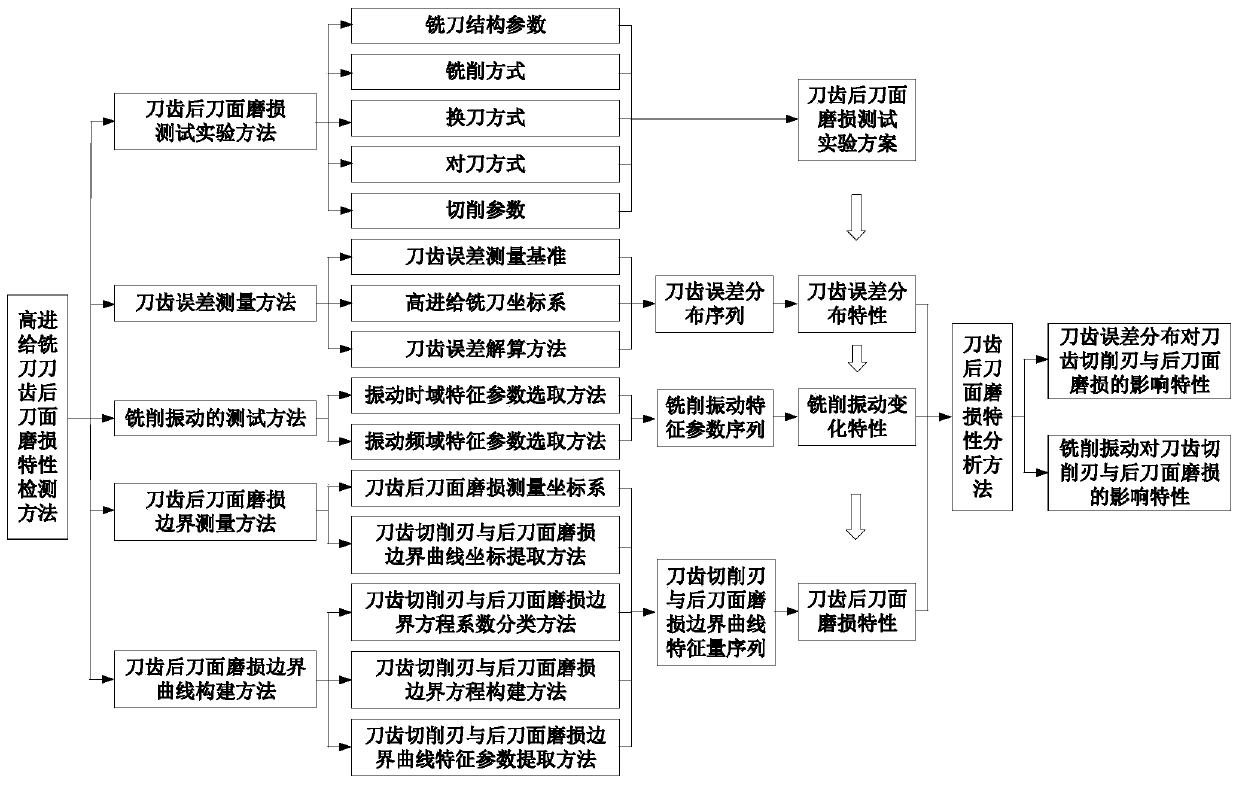
[0104] A detection method for the flank wear characteristics of high-feed milling cutter teeth, such as figure 1 shown, including the following steps:

[0105] Step a. Perform a high-feed milling cutter flank wear test, determine the milling cutter structural parameters, milling method, tool change method, tool setting method and cutting parameters, and obtain the high-feed milling cutter flank wear state ;

[0106] Step b, measuring the structure of the high-feed milling cutter and its tooth error, establishing the coordinate system of the high-feed milling cutter, determining the tooth error reference and the formula for calculating the tooth error of the milling cutter, and obtaining the distribution characteristics of the tooth error of the milling cutter;

[0107] Step c, performing the cutting vibration test of the high-feed milling cutter, realizing the extraction and selection of the characteristic parameters of the milling vibration signal, obtaining the characteristic...

specific Embodiment approach 2

[0118] Specifically, on the basis of Embodiment 1, the method for testing the flank wear of high-feed milling cutter teeth includes the following steps:

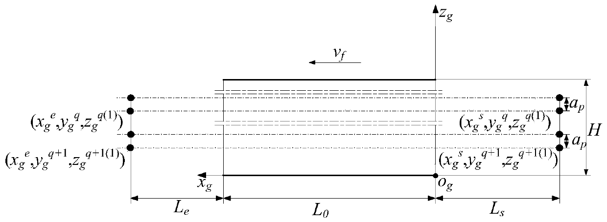
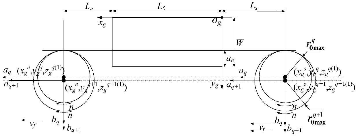
[0119] Step a1. In order to avoid the influence of the heat-mechanical coupling field dissipation of the milling cutter caused by stopping the machine to measure the tool wear on the accuracy of the cutter tooth wear test data, and at the same time, to avoid the influence of the milling cutter mode change on the vibration caused by the tool change, the same A high-feed milling cutter body and the same installation and positioning method, by replacing a group of new inserts of the same specification for each group of experiments, and performing multiple consecutive axial layered cuttings under different cutting stroke conditions, the corresponding The flank wear state of high-feed milling cutter teeth under the cutting stroke, the tool change method is as follows figure 2 shown;

[0120] Step a2. After changing the blade ea...

specific Embodiment approach 3

[0134] Specifically, on the basis of the second specific embodiment, the high-feed milling cutter structure and the method for measuring the tooth error thereof include the following steps:

[0135] Step b1. Considering that the tool change method in the second embodiment causes the different tooth error distribution of each milling cutter to affect the milling cutter tooth wear and milling vibration, before the start of each group of experiments, the high-feed milling cutter Carry out tooth error measurement. A high-feed milling cutter tooth error measurement method is proposed: take the intersection of the tangent plane at the lowest point of the high-feed milling cutter tooth along the axial direction and the milling cutter axis as the origin, and establish a high-feed milling cutter coordinate system; The tool tip rotates in turn until it coincides with the a-axis, and at the same time, measure the distance from the lowest point of each tooth along the axial direction to t...


PUM


Abstract

The invention discloses a method for detecting cutter tooth flank surface wear characteristics of a high-feed milling cutter, and belongs to the field of milling cutter detection. Cutter tooth flank surface wear characteristics cannot be completely revealed in the prior art. The method comprises the steps of carrying out cutter tooth flank surface wear testing of the high-feed milling cutter to obtain a cutter tooth flank surface wear state, carrying out structure and cutter tooth error measurement to obtain cutter tooth error distribution characteristics, carrying out cutting vibration testing to obtain variation characteristics of milling vibration signals, carrying out cutter tooth flank surface wear boundary measurement to obtain cutter tooth cutting edge and flank surface wear boundary curve coordinate values, constructing a cutter tooth flank surface wear boundary curve, extracting cutter tooth cutting edge and flank surface wear boundary curve characteristic parameters, and analyzing cutter tooth flank surface wear characteristics to obtain the influence characteristics of the cutter tooth error distribution on cutter tooth cutting edge and flank surface wear and obtain theinfluence characteristics of the milling vibration on cutter tooth cutting edge and flank surface wear. The change characteristics of the cutter tooth cutting edge and flank surface wear along with the cutting stroke can be completely revealed.

Description

technical field [0001] The invention belongs to the field of milling cutter detection, and in particular relates to a detection method for the flank wear characteristics of high-feed milling cutter teeth. Background technique [0002] High-feed milling cutter is a typical high-efficiency cutting tool, which is widely used in large-scale titanium alloy machining. When using this kind of milling cutter to process large titanium alloy structural parts, due to the influence of cutter tooth error distribution and milling vibration, the problems of excessive cutting edge stress and fast wear of cutter teeth are prominent. [0003] The existing high-feed milling cutter tooth wear test experiment adopts the method of stopping the machine to measure the tool wear, ignoring the influence of the thermal coupling field dissipation of the milling cutter on the accuracy of the cutter tooth flank wear test data, and the milling cutter caused by tool change. The influence of modal changes ...

Claims


Application Information

Patent Timeline
Patent Type & Authority Applications(China)
IPC IPC(8): B23Q17/09
Inventor 姜彬左林涵赵培轶丁旺
Owner HARBIN UNIV OF SCI & TECH
Why Eureka
Try Eureka