Cassette clamping mechanism

A technology of splint and clamping arm, which is applied in the design of semiconductor manufacturing field, can solve the problems of inability to effectively identify the position and height of the crystal boat, cannot be clamped, and damage the crystal boat, etc., and achieve the limit automatic alarm function and safe shutdown. Effective and precise gripping effect

Inactive Publication Date: 2019-06-28
昆山基侑电子科技有限公司
View PDF9 Cites 2 Cited by
  • Summary
  • Abstract
  • Description
  • Claims
  • Application Information

AI Technical Summary

Problems solved by technology

[0003] The existing crystal boat clamping mechanism uses a clamping force perpendicular to the direction of the crystal boat to clamp the crystal boat, but it is found in actual use that the clamping mechanism often fails to clamp or touches the wafer when the clamping mechanism clamps the wafer downward. The reason for the damage to the crystal boat is related to the inability of the clamping mechanism to effectively identify the position and height of the wafer boat before going down

Method used


Image

  • Cassette clamping mechanism
  • Cassette clamping mechanism
  • Cassette clamping mechanism

Examples


Embodiment 1

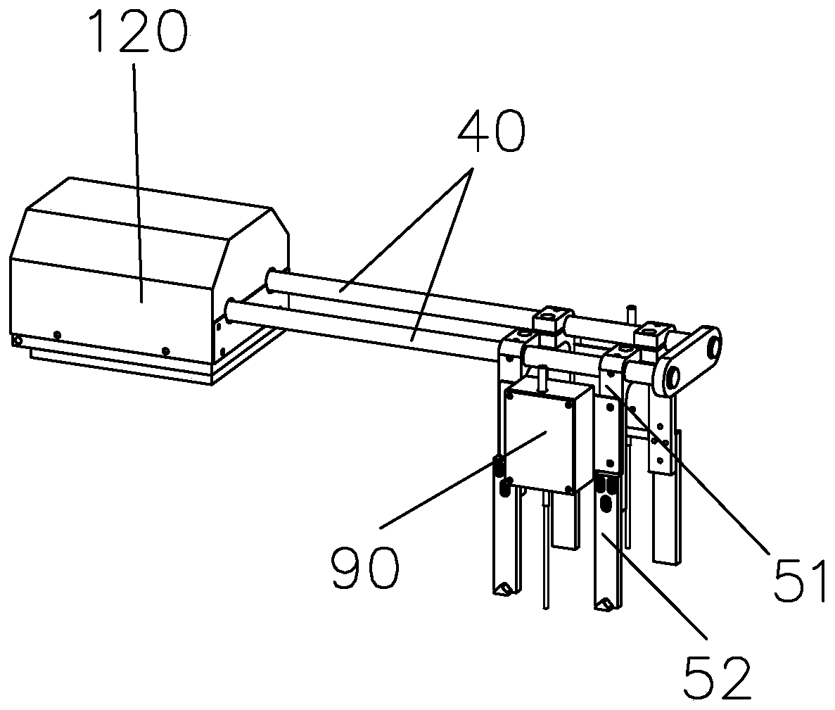
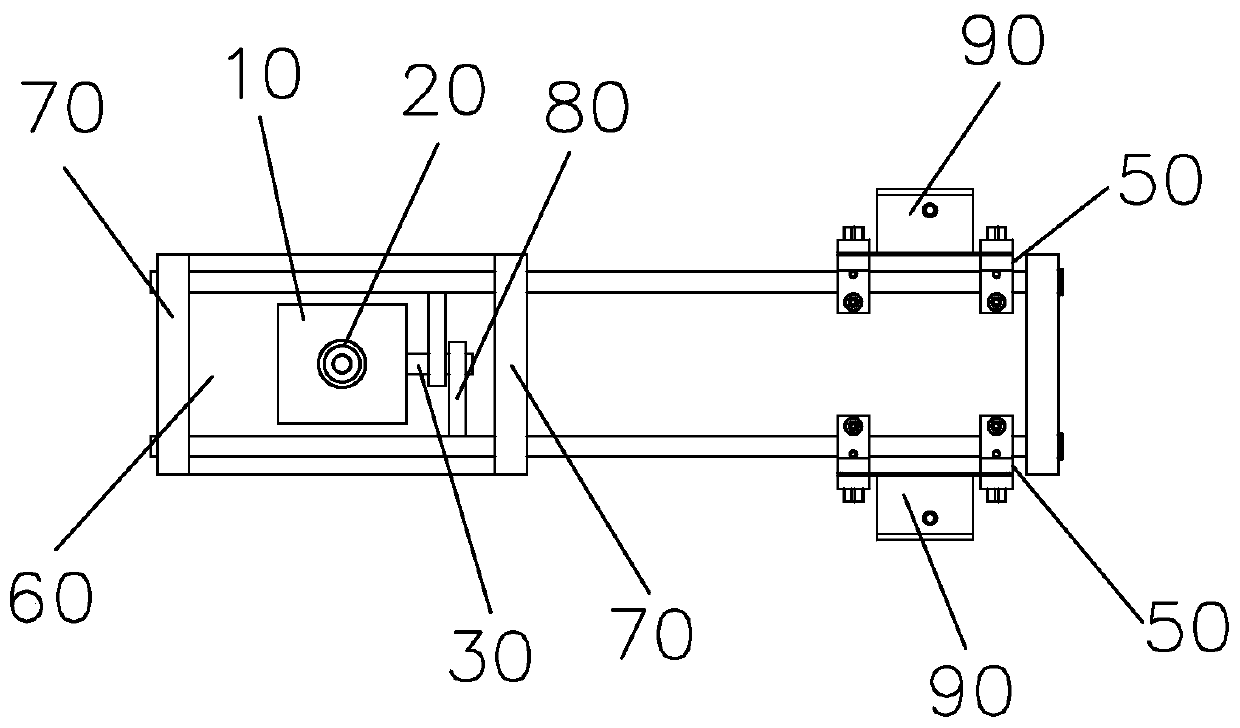
[0024] figure 1 and 2 The wafer clamping mechanism shown includes a screw stepping motor 10, a bushing 20, a connecting shaft 30, two shafts 40 and a pair of clamping arms 50, and the screw stepping motor 10 is fixed on a bottom plate 60 , two parallel bearing seats 70 are arranged on the bottom plate 60 . The shaft sleeve 20 is installed on the screw shaft of the screw stepping motor 10, the connecting shaft 30 is perpendicular to the screw shaft, and the shaft sleeve 20 lifts together with the connecting shaft 30 when lifting along the screw shaft; the two shaft rods 40 and the The connecting shaft 30 is parallel and arranged on both sides of the connecting shaft 30 respectively, and the shaft rod 40 is inserted into the bearing hole of the bearing seat 70, and one end of the shaft rod 40 is provided with a connecting plate 80 which is movably sleeved on the connecting shaft 30, and a pair of clips The holding arms 50 are respectively fixed on the other ends of the two sha...

Embodiment 2

[0029] This embodiment is based on Embodiment 1.

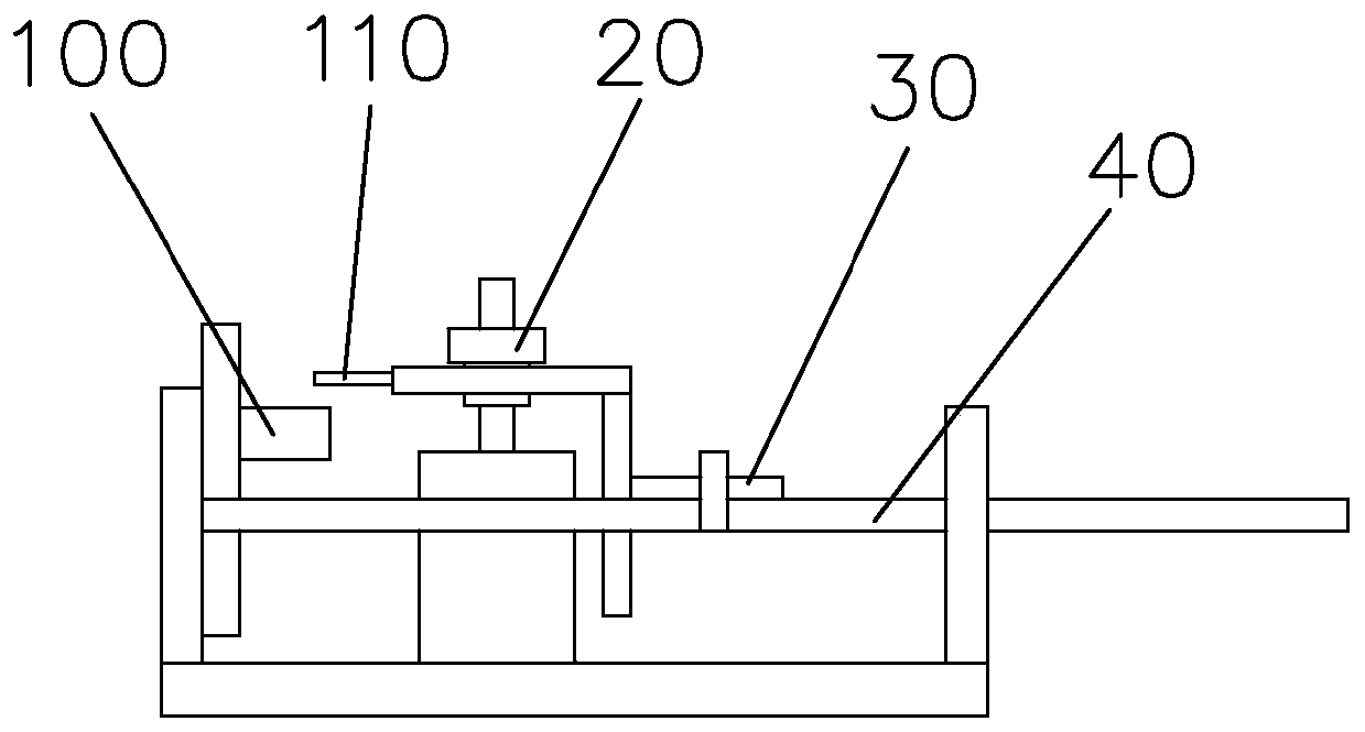
[0030] A photoelectric switch 100 is arranged on the side of the screw stepping motor 10 , and a positioning block 110 used in conjunction with the photoelectric switch 100 is arranged on the bushing 20 . The screw stepping motor 10 reads the positioning pulse in the PLC, and cooperates with the photoelectric switch 100 to effectively and accurately grip the wafer boat and basket, and realize the limit automatic alarm function and safe shutdown.


PUM


Abstract

In order to solve the technical problem that a clamping mechanism cannot clamp the cassette or is easy to hit and damage the cassette when clamping a cassette downwards, the invention provides a cassette clamping mechanism comprising a screw rod stepping motor, a shaft sleeve, a connecting shaft, two shaft rods and a pair of clamping arms. The connecting shaft is perpendicular to a screw rod shaft; the shaft sleeve carries the connecting shaft to lift up and lower down when lifting up and lowering down along the screw rod shaft; the two shaft rods and the connecting shaft are in parallel and are arranged on two sides of the connecting shaft; a connecting plate movably arranged on the connecting shaft in a sleeving way is arranged at one ends of the shaft rods; the pair of clamping arms arefixed to the other ends of the two shaft rods; a driving lever switch is arranged in each clamping arm; and a driving lever of each driving lever switch downwards extends to the lower part of the corresponding clamping arm. The screw rod stepping motor and the shaft sleeve drive the pair of clamping arms to rotate and contract inwards and rotate and open outwards, so that the cassette can be stably clamped; and in addition, the driving lever switches are always located above the cassette before the clamping mechanism moves downwards, so that the position and the height of the cassette can beeffectively identified.

Description

technical field [0001] The invention relates to the technical field of semiconductor manufacturing, and mainly relates to wafer manufacturing equipment, especially for wafer boat clamping mechanisms. Background technique [0002] In the manufacturing plants of the semiconductor industry, multiple wet process equipments are usually configured to process a large number of wafers in batches. In order to meet the types of electronic products, wafers or substrates of different shapes and sizes are used. Therefore, when performing the wet process, the types of cas setters used will also be different. For example, when a 4-inch or 6-inch substrate is used for a wet process, generally a wafer boat of a corresponding size is used to carry the substrate. [0003] The existing crystal boat clamping mechanism uses a clamping force perpendicular to the direction of the crystal boat to clamp the crystal boat, but it is found in actual use that the clamping mechanism often fails to clamp...

Claims


Application Information

Patent Timeline
Patent Type & Authority Applications(China)
IPC IPC(8): B65G47/90
Inventor 王静强徐福兴黄锡钦
Owner 昆山基侑电子科技有限公司
Why Eureka
Try Eureka