Fuel tank control valve

A technology for controlling valves and fuel tanks, which is applied in the direction of valve lifts, valve details, and valve devices. It can solve problems such as internal and external pressure differences, gaskets cannot be separated in time, and affect normal exhaust, and achieve the effect of improving reliability.

Pending Publication Date: 2019-06-28
JIANGSU AOLIWEI SENSING TECH
View PDF0 Cites 1 Cited by
  • Summary
  • Abstract
  • Description
  • Claims
  • Application Information

AI Technical Summary

Problems solved by technology

[0002] The fuel tank control valve (FLVV valve) is installed on the top of the fuel tank assembly. In the prior art, the fuel tank control valve includes a float arranged in the valve body. The top of the valve body is provided with a vent hole, and the top of the float is set in line with the vent hole. With the matching gasket, the float rises with the liquid level under the buoyancy of the fuel, so that the gasket closes the vent hole. When the fuel level drops, the float drops under the action of gravity, so that the gasket is separated from the vent hole, and the ventilation is completed. , the disadvantage is that the gasket cannot be separated in time due to the internal and external pressure difference generated when the gasket closes the exhaust hole, thus affecting the normal exhaust.

Method used


Image

  • Fuel tank control valve
  • Fuel tank control valve
  • Fuel tank control valve

Examples


Embodiment 1

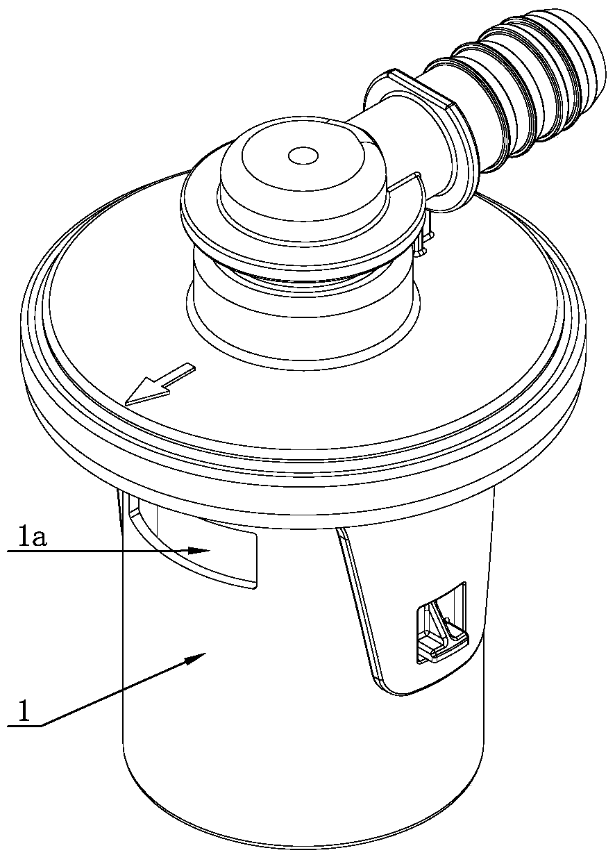
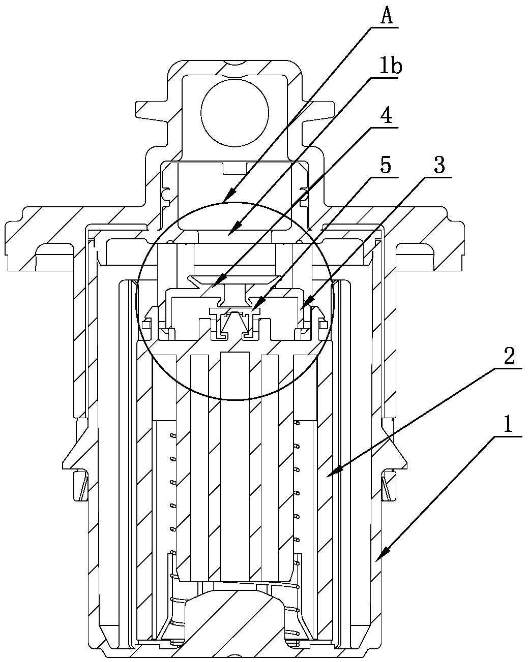
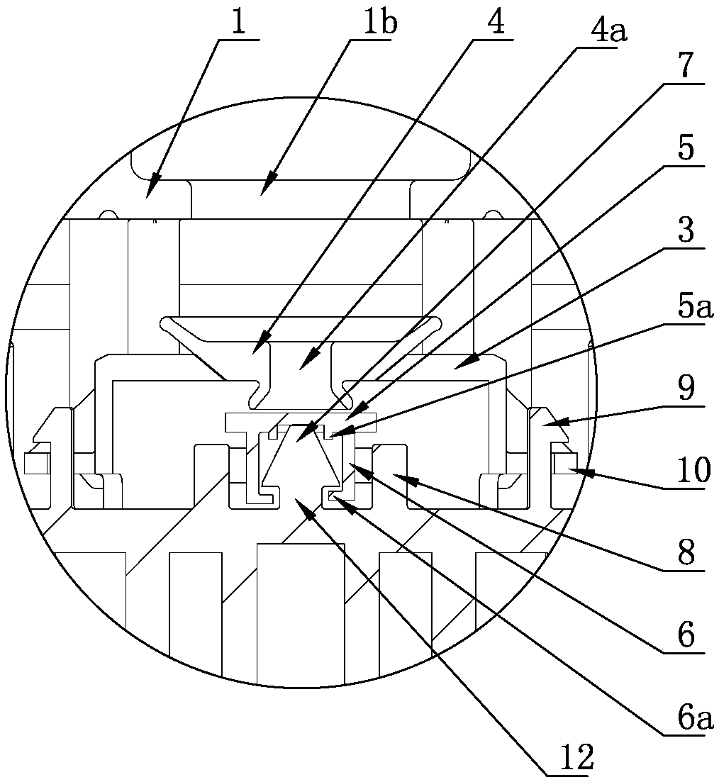
[0020] like Figure 1-6 The shown fuel tank control valve includes a float 2 arranged in the valve body 1, the top of the valve body 1 is provided with an exhaust hole 1b, the side of the valve body 1 is provided with a liquid inlet hole 1a, and the bottom of the valve body 1 is provided with a The oil discharge hole, the top surface of the float 2 is equipped with a sealing cover 5, the outer periphery of the top of the float 2 is provided with a support frame 3, and the center of the support frame 3 is installed with a sealing gasket 4 that cooperates with the sealing cover 5 and the exhaust hole 1b, and the center of the sealing gasket 4 is There is a vent hole 4a, the top and bottom of the gasket 4 are processed into a trumpet-shaped structure, the top of the gasket 4 is matched with the vent hole 1b, the bottom of the gasket 4 is matched with the sealing cover 5, and the sealing cover 5 is passed through the push-pull assembly It is movably installed on the top of the flo...

Embodiment 2

[0022] like Figure 1-5 A fuel tank control valve shown in . There is an oil discharge hole, a sealing cover 5 is installed on the top surface of the float 2, a support frame 3 is set on the outer periphery of the top of the float 2, and a sealing gasket 4 is installed in the center of the support frame 3 to cooperate with the sealing cover 5 and the exhaust hole 1b. 4 is provided with a ventilation hole 4a in the center, the top and bottom of the gasket 4 are processed into a trumpet-shaped structure, the top of the gasket 4 is matched with the vent hole 1b, the bottom of the gasket 4 is matched with the sealing cover 5, and the sealing cover 5 is The push-pull assembly is movably installed on the top of the float 2. The push-pull assembly is used to push the seal cover 5 to move upward when the float 2 rises. When the float 2 descends, one side of the seal cover 5 pulls it down. The push-pull assembly includes a Pillar 12, a boss 7 is arranged on the pillar 12, a pair of gu...


PUM


Abstract

The invention discloses a fuel tank control valve, and belongs to the field of valves. The fuel tank control valve comprises a floater arranged in a valve body, an exhaust hole is formed in the top ofthe valve body, a liquid inlet hole is formed in the side part of the valve body, a sealing cover is arranged on the top surface of the floater, a supporting frame is arranged on the periphery of thetop of the floater in a sleeve mode, a sealing gasket matched with the sealing cover and the exhaust hole is arranged in the center of the supporting frame, a vent hole is formed in the center of thesealing gasket, the top and the bottom of the sealing gasket are both machined into a trumpet-shaped structure, the top of the sealing gasket is matched with the exhaust hole, the bottom of the sealing gasket is matched with the sealing cover, the sealing cover is movably arranged at the top of the floater through a push-and-pull assembly, and the push-and-pull assembly is used for pushing the sealing cover to move upwards when the floater rises, and pulling one side of the sealing cover to descend when the floater descends. According to the fuel tank control valve, the sealing gasket can bestably separated from the exhaust hole through the designed push-and-pull assembly, so that influence from the internal and external pressure difference is avoided, the use reliability of the valve body is improved, and the control valve can be used in a fuel tank.

Description

technical field [0001] The invention relates to a valve, in particular to an FLVV valve. Background technique [0002] The fuel tank control valve (FLVV valve) is installed on the top of the fuel tank assembly. In the prior art, the fuel tank control valve includes a float arranged in the valve body. The top of the valve body is provided with a vent hole, and the top of the float is set in line with the vent hole. With the matching gasket, the float rises with the liquid level under the buoyancy of the fuel, so that the gasket closes the vent hole. When the fuel level drops, the float drops under the action of gravity, so that the gasket is separated from the vent hole, and the ventilation is completed. , its shortcoming is that, because the sealing gasket will produce internal and external pressure difference when sealing the exhaust hole, the sealing gasket cannot be separated in time, thus affecting the normal exhaust. Contents of the invention [0003] The purpose of ...

Claims


Application Information

Patent Timeline
Patent Type & Authority Applications(China)
IPC IPC(8): F16K1/00F16K31/20B60K15/035
Inventor 李冬梅邓广森李艮春吴晓东陈斌高计超张冠中
Owner JIANGSU AOLIWEI SENSING TECH
Why Eureka
Try Eureka