Lightweight special vehicle body

A special vehicle and lightweight technology, applied in the field of car body, can solve the problems that cannot meet the needs of modern military, can not meet the lightweight requirements of special vehicles, and the light weight of all-welded steel car body is poor, so as to achieve high rigidity and low The effect of simple setting of car body weight and skeleton structure

Inactive Publication Date: 2019-06-28
JIANGLU MACHINERY & ELECTRONICS GROUP
4 Cites 0 Cited by

AI-Extracted Technical Summary

Problems solved by technology

The weight of the above-mentioned all-welded steel car body is relatively poor, and cannot meet the lightweight requirements of special vehicles
The above-mentioned aluminum alloy fully welded car body sh...

Method used

As shown in Figure 1-Fig. 4, concrete structure of the present invention is: car body shell adopts 7B52 and 7A52 armored aluminum alloy as car body deck material, adopts box-type welded structure, by first upper deck 1, first lower deck Deck 9, power cabin deck 8, top deck 3, stern deck 5, bottom deck 4, side upper deck 6, side lower deck 2, etc. are welded by armor plates of different thickness specifications, of which the first upper deck 1, the lower deck Deck 9, side upper dec...

Abstract

The invention discloses a lightweight special vehicle body. The lightweight special vehicle body comprises a shell and a framework, wherein the shell comprises a thin-wall structure formed by weldinga first upper deck, a first lower deck, a power cabin deck, a top deck, a tail deck, a bottom deck, a side upper deck and a side lower deck; the framework comprises vehicle body toggle plates, a vehicle body torsion bar protective cover, stand columns, a seat ring seat and a U-shaped rib; the vehicle body toggle plates are arranged on a horizontal deck on the left side and the right side of a vehicle body; the top of each vehicle body toggle plate is connected with a reinforcing rib on the top deck; the plurality of vehicle body toggle plates are arranged from front to back; the vehicle body torsion bar protective cover, a vehicle body balance elbow support and the U-shaped reinforcing ribs on the bottom deck are welded together to form a bottom deck frame; the stand columns are distributed on the peripheral ring of the seat ring seat; the bottom of each stand column is arranged on the U-shaped ribs; the top of each stand column is connected with the seat ring seat; and the vehicle body toggle plates, the vehicle body torsion bar protective body, the stand columns, the seat ring seat and the U-shaped ribs form a full-frame structure. According to the lightweight special vehicle body, the rigidity and strength of the vehicle body are effectively improved, and lightweight effect is great on the premise that the relevant indexes are met by the performance.

Application Domain

Armoured vehicles

Technology Topic

Image

  • Lightweight special vehicle body
  • Lightweight special vehicle body
  • Lightweight special vehicle body

Examples

  • Experimental program(1)

Example Embodiment

[0017] In order to make the above-mentioned objects, features and advantages of the present invention more obvious and understandable, the specific embodiments of the present invention will be described in detail below. In the following description, many specific details are explained in order to fully understand the present invention. However, the present invention can be implemented in many other ways different from those described herein, and those skilled in the art can make similar improvements without departing from the connotation of the present invention. Therefore, the present invention is not limited by the specific implementation disclosed below.
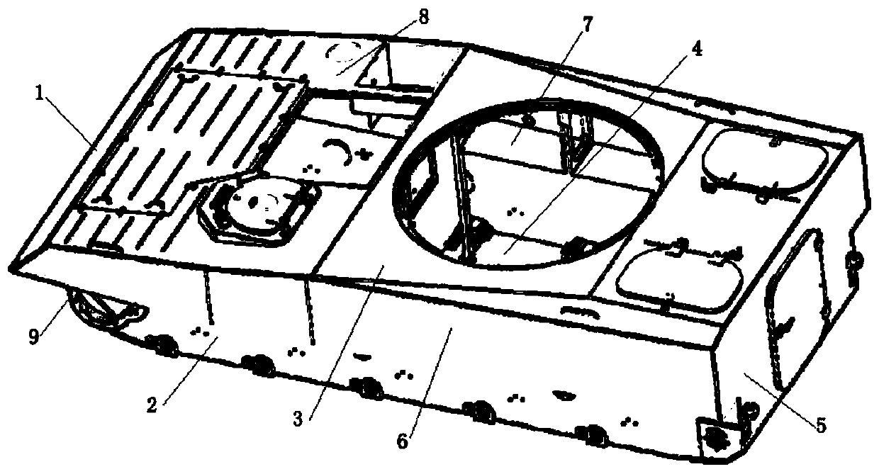
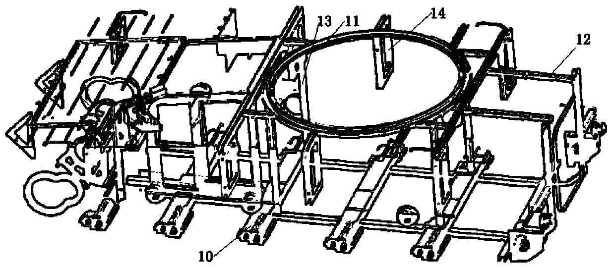
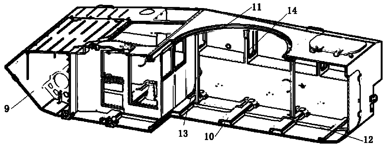
[0018] Such as Figure 1-Figure 4 As shown, the specific structure of the present invention is: the car body shell adopts 7B52 and 7A52 armored aluminum alloy as the car body deck material, adopts a box-type welding structure, and consists of a first upper deck 1, a first lower deck 9, a power cabin deck 8, and a top deck. Deck 3, tail deck 5, bottom deck 4, side upper deck 6, side lower deck 2 and other armor plates of different thickness specifications are welded together. Among them, the first upper deck 1, the lower bow deck 9, the side upper deck 6, the side The lower deck 2 and the tail deck 5 use 7B52 armored aluminum plates, and the other decks are 7A52 armored aluminum plates. According to the angles of various parts of the car body, the thickness of the deck and the force, the main welding seam of the car body is designed, and the deck groove form is determined accordingly. According to the force distribution of the car body, reinforcement ribs are added at some welds to ensure the structural strength of the car body welds.
[0019] The car body is a thin shell structure. The rigidity and strength of the car body are mainly ensured by the rational design of the skeleton and stiffeners. The top deck 3, bottom deck 4, and tail deck 5 of the car body adopt a variety of U-shaped ribs 12 To form a frame structure, a plurality of car body brackets 14 are arranged on the horizontal deck 7, annular ribs are arranged at the bottom of the seat ring seat 11, and 4 pillars 13 are arranged under the annular ribs for support. The car body bracket 14 adopts a "mouth"-shaped structure. The car body bracket 14 is welded by a front panel 141, a rear panel 142 and a "mouth"-shaped stiffener 143. The car body bracket 14 is used to improve the front rigidity of the car body , The brackets on both sides of the gun are used to transmit the turret load. Two U-shaped large transverse ribs 12 are arranged on the front and rear of the seat ring seat 11, and the transverse ribs are connected with four brackets on both sides to form a frame structure.
[0020] It should be noted that in this article, the terms "include", "include" or any other variants thereof are intended to cover non-exclusive inclusion, so that a process, method, article or device including a series of elements not only includes those elements, It also includes other elements not explicitly listed, or elements inherent to the process, method, article, or equipment.
[0021] Specific examples are used in this article to illustrate the principle and implementation of the present invention. The description of the above examples is only used to help understand the method and core idea of ​​the present invention. The above are only the preferred embodiments of the present invention. It should be pointed out that due to the limited expression of words, there are objectively infinite specific structures. For those of ordinary skill in the art, the principle of the present invention is not deviated from the premise Next, several improvements, modifications or changes can also be made, or the above technical features can be combined in an appropriate manner; these improvements, changes or combinations, or the concept and technical solution of the invention can be directly applied to other occasions without improvement , Should be regarded as the protection scope of the present invention.

PUM

no PUM

Description & Claims & Application Information

We can also present the details of the Description, Claims and Application information to help users get a comprehensive understanding of the technical details of the patent, such as background art, summary of invention, brief description of drawings, description of embodiments, and other original content. On the other hand, users can also determine the specific scope of protection of the technology through the list of claims; as well as understand the changes in the life cycle of the technology with the presentation of the patent timeline. Login to view more.

Similar technology patents

GMT rear floor structure of small vehicle

Owner:ANHUI JIANGHUAI AUTOMOBILE GRP CORP LTD

Multifunctional offensive and defensive shield

ActiveCN109029117AReduce body weightDisintegrate the will to resistArmour platesShieldsSteel platesMaterials science
Owner:袁炜澎

Classification and recommendation of technical efficacy words

Why Eureka
Try Eureka