

Method for manufacturing air chamber auto body
A technology of automobile body and manufacturing method, which is applied in the field of manufacturing technology of automobile body materials, can solve problems such as insecurity for drivers and passengers, complicated manufacturing process, difficult repair, etc., to reduce power demand and energy consumption, reduce production cost, reduce The effect of body weight
- Summary
- Abstract
- Description
- Claims
- Application Information
AI Technical Summary
Problems solved by technology
Method used
Image

Examples
Embodiment Construction
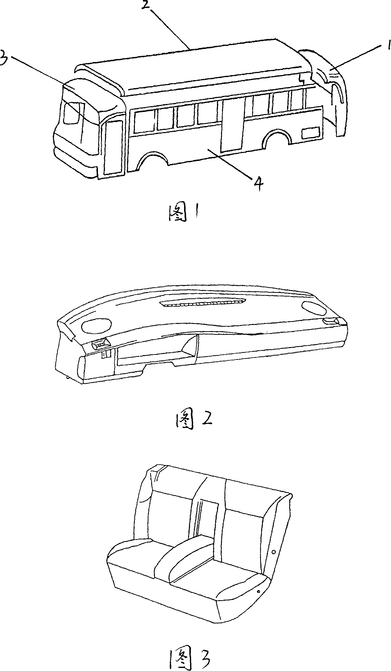
[0010] Below in conjunction with accompanying drawing description and example, the present invention is described in further detail
[0011] As shown in Figure 1, the front 1, the roof 2, the rear 3, and the side of the vehicle body 4 are heat-synthesized respectively by the above-mentioned method, and then the various parts are connected and fixed to form an airbag-type bus body structure, and the inflation valve is inflated respectively. Just form an airbag type passenger car.
[0012] As shown in Figure 2, before making the airbag body, the model is designed first, and then the mold is made, and then the composite rubber material is placed on the mold and hot-pressed. When hot pressing, the outer layer material can be placed in the mold for hot pressing, and then the drawstring (explosion-proof rib) is heat-sealed to the outer shell layer, and then the inner layer is heat-sealed to all the many drawstrings. This forms a rubber monolithic body shell. An inflation valve is ...
PUM
 Abstract
Description
Claims
Application Information