Portable bridge crack width measuring instrument

A crack width, portable technology, applied in the direction of mechanical gap measurement, etc., can solve the problems of poor accuracy, large limitations, high degree of personal subjectivity, etc., and achieve the effect of facilitating popularization and application, ensuring accuracy, and being easy to carry

Active Publication Date: 2019-06-28
田泽宇
View PDF8 Cites 2 Cited by
  • Summary
  • Abstract
  • Description
  • Claims
  • Application Information

AI Technical Summary

Problems solved by technology

The traditional method of detecting cracks based on artificial vision is increasingly unable to meet the requirements of the development of bridge detection, mainly due to the high degree of personal subjectivity and poor accuracy, and some large-scale equipment is not suitable for the detection of bridges
[0004] In the existing technology, such as a portable bridge crack width simple measuring instrument disclosed in the Chinese patent (authorized announcement number: CN 205482870 U), it can only measure the surface crack width of the bridge, and cannot directly measure the internal crack width of the bridge. measurement, limited

Method used


Image

  • Portable bridge crack width measuring instrument
  • Portable bridge crack width measuring instrument
  • Portable bridge crack width measuring instrument

Examples


Embodiment 1

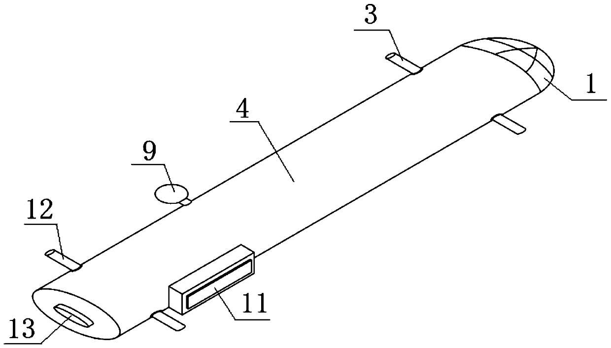
[0029] see Figure 1-4 , in an embodiment of the present invention, a portable bridge crack width measuring instrument includes a cylinder 4, one end of the cylinder 4 is a measuring end, and a measuring assembly 3 is arranged inside the measuring end of the cylinder 4, and the cylinder 4 The other end is the observation end, the observation end of the cylinder 4 is provided with an observation assembly 12, the measurement assembly 3 and the observation assembly 12 all include a measuring rod 14 that can extend from the side wall of the cylinder 4, the cylinder The observation end of 4 is also provided with a control assembly that can make the measurement assembly 3 and the measurement rod 14 of the observation assembly 12 protrude synchronously.

[0030] Further, the barrel 4 may be a cylindrical barrel structure with both ends closed, or other structures.

[0031] Further, in order to facilitate observation of the inside of the crack, a spotlight 2 is installed at the measu...

Embodiment 2

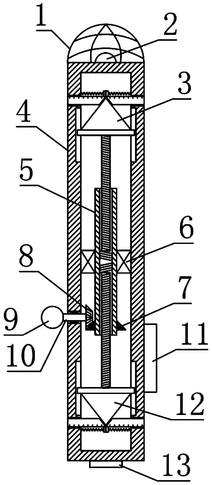
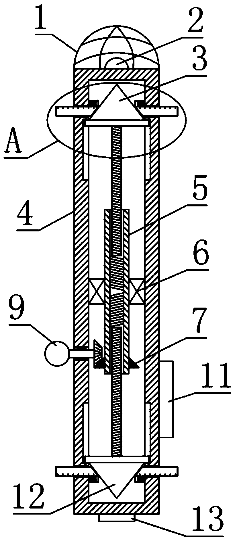
[0033] see Figure 2-4 , the difference between this embodiment and embodiment 1 is:

[0034]In this embodiment, the measurement assembly 3 and the observation assembly 12 both include a top block 17 arranged on the inside of the cylinder body 4, and the two top blocks 17 are arranged symmetrically. The front view of the top block 17 is in the shape of an isosceles triangle. A guide plate 18 is installed and fixed at the inner end of the cylinder body 4. A chute 22 that is slidably connected with the guide plate 18 is provided on the inner side wall of the cylinder body 4. The guide plate 18 can slide along the chute 22. The inner side of the guide plate 18 A screw rod 21 is installed and fixed; the control assembly includes a rotating ball head 9, a rotating rod 10, a driving bevel gear 8, a driven bevel gear 7, a bearing 6 and a threaded cylinder 5, and the inner middle part of the cylinder body 4 rotates through the bearing 6 A threaded barrel 5 is installed, and the threa...


PUM


Abstract

The invention relates to the field of building detection tools, in particular to a portable bridge crack width measuring instrument. The portable bridge crack width measuring instrument comprises a cylinder body, wherein one end of the cylinder body is a measuring end; a measuring assembly is arranged inside the measuring end of the cylinder body, and the other end of the cylinder body is an observation end; an observation assembly is arranged inside the observation end of the cylinder body, and each of the measurement assembly and the observation assembly comprises a measuring rod which can extend from the side wall of the cylinder body; and the observation end of the cylinder body is also provided with a control assembly capable of enabling the measuring assembly and a measuring rod of the observation assembly to synchronously extend out. The portable bridge crack width measuring instrument is convenient to operate, simple in structure and easy to carry, and can perform visual comparison measurement on the width of the inside of a crack on a bridge, accuracy is guaranteed, and thus, the portable bridge crack width measuring instrument is beneficial to popularization and application.

Description

technical field [0001] The invention relates to the field of building testing equipment, in particular to a portable bridge crack width measuring instrument. Background technique [0002] Bridges generally refer to structures erected on rivers, lakes and seas to allow vehicles and pedestrians to pass smoothly. In order to adapt to the modern high-speed development of the transportation industry, bridges are also extended to buildings that cross mountain streams, poor geology or meet other transportation needs to make traffic more convenient. A bridge is generally composed of a superstructure, a substructure, a support and ancillary structures. The superstructure is also called a bridge span structure, which is the main structure for crossing obstacles; the substructure includes abutments, piers and foundations; Or the force transmission device installed at the supporting place of the bridge abutment; the auxiliary structures refer to the bridge head board, conical slope pro...

Claims


Application Information

Patent Timeline
Patent Type & Authority Applications(China)
IPC IPC(8): G01B5/14
Inventor 田泽宇史恩波王静霞赵备郑亚刘俊峦符雨萌
Owner 田泽宇
Why Eureka
Try Eureka