
Circuit emergency protection device

A protection device and emergency technology, which is applied in the direction of emergency protection devices, circuits, protection switches, etc., can solve problems such as failure to continue to use, fuse damage, etc., and achieve cost saving, convenient operation, and simple equipment structure.

Active Publication Date: 2019-06-28
江苏信实电气有限公司
View PDF8 Cites 5 Cited by
  • Summary
  • Abstract
  • Description
  • Claims
  • Application Information

AI Technical Summary

Problems solved by technology

[0002] As we all know, electricity is a very common resource. It plays a pivotal role in life. Today's life is basically inseparable from power resources. With the development and application of new power generation equipment such as wind power, today's The society has basically met the demand for electricity. With the popularization and application of power equipment, the power safety issues involved have always been a topic of frequent discussion. In order to protect power equipment and personal safety, many parts such as fuses are being widely used. It is used in various fields. Although it has the function of protecting electrical equipment, it is a one-time-use item. In general, the fuse will cause damage in the event of a circuit failure. As long as a circuit failure occurs, the fuse will be damaged. Unable to continue to use, if you need to continue to use the electric equipment, you need to replace the fuse

Method used


Image

  • Circuit emergency protection device
  • Circuit emergency protection device
  • Circuit emergency protection device

Examples


Embodiment Construction

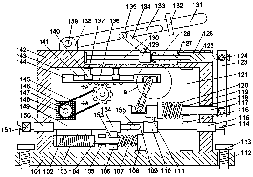
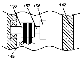
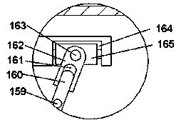
[0014] Combine below Figure 1-3 The present invention is described in detail, wherein, for the convenience of description, the orientations mentioned below are defined as follows: figure 1 The up, down, left, right, front and back directions of the projection relationship itself are the same.

[0015] Such as Figure 1-3 As shown, a circuit emergency protection device of the present invention includes a bottom plate 101 extending left and right and a device frame 142 extending left and right on the top end of the bottom plate 101. The bottom plate 101 is symmetrically provided with screw grooves 112 communicating up and down. The screw groove 112 is threadedly connected with a fixing screw 113 extending up and down, and the top end surface of the device frame 142 is fixed with a shaft frame 138, and the shaft frame 138 is connected with a rotating shaft 139 extending forward and backward in rotation, and the rotating shaft 139 is fixed. Connected with a left and right exten...


PUM


Abstract

The invention discloses a circuit emergency protection device which comprises a bottom plate extending left and right and a device frame extending left and right at the top end surface of the bottom plate. The bottom plate is symmetrically provided with vertical through screw slots at left and right sides, fixed screws extending up and down are in a thread fit connection with the screw slots, thetop end surface of the device frame is fixedly provided with a rotating shaft frame which is in rotating fit connection with a front and back extending rotating shaft, the rotating shaft is fixedly connected to a left and right extending rotating handle rod, the right end surface of the rotating handle rod is fixedly provided with a stopper, the right end surface of the stopper is fixedly providedwith a left and right extending handle rod, and the bottom of the rotating handle rod is provided with a left and right extending groove with a downward opening. The circuit emergency protection device has the advantages of simple structure and convenient operation, two corresponding protection mechanisms are set according to common open circuit and short circuit conditions in the circuit, and the practicability of the device is improved.

Description

technical field [0001] The invention relates to the technical field of circuit protection devices, in particular to a circuit emergency protection device. Background technique [0002] As we all know, electricity is a very common resource. It plays a pivotal role in life. Today's life is basically inseparable from power resources. With the development and application of new power generation equipment such as wind power, today's The society has basically met the demand for electricity. With the popularization and application of power equipment, the power safety issues involved have always been a topic of frequent discussion. In order to protect power equipment and personal safety, many parts such as fuses are being widely used. It is used in various fields. Although it has the function of protecting electrical equipment, it is a one-time-use item. In general, the fuse will cause damage in the event of a circuit failure. As long as a circuit failure occurs, the fuse will be da...

Claims


Application Information

Patent Timeline
IPC IPC(8): H01H71/02H01H71/24H01H71/42H01H83/12
Inventor 余丹丹
Owner 江苏信实电气有限公司
Learn More