


Quick Research
Generate reliable direction feasibility study reports for your R&D in just a few steps.

Technical Q&A
Discover and master advanced knowledge NOW. Basics, ideas, possibilities, all at once.

Find Solutions
As an expert in R&D theories, this can generate solutions to your technical problems instantly.

Evaluate Feasibility
Analyze your overall solution with one click, know your potential R&D risks in advance.

Monitor Landscape
Get weekly tech updates, stay abreast of the latest tech innovations and key insights.
Implantable monitor introducer
A technology for guides and monitors, applied in the direction of sensors, anatomical instruments, diagnostic recording/measurement, etc., can solve problems such as poor performance
- Summary
- Abstract
- Description
- Claims
- Application Information
AI Technical Summary
Problems solved by technology
Method used
Image

Examples
Embodiment Construction
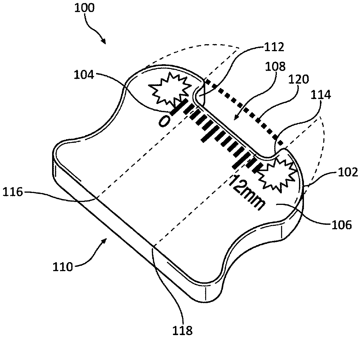
[0050] Implantable monitors can be configured to monitor various physiological parameters and / or provide therapy to a patient. Implantable monitors may be implanted subcutaneously in an implant site or pocket in the chest or abdominal cavity of a patient. An inappropriate implant location may result in poor acquisition of physiological parameters and / or inability to deliver therapy. Improper balloon formation may result in ejection of the implant device from the balloon. Various aspects of the present disclosure relate to facilitating placement of implantable monitors within a patient. For example, various aspects relate to facilitating an operative balloon forming configuration (eg, depth, width, length, and angle) and an operative balloon location for an implantable monitor.
[0051] figure 1 An example introducer 100 is shown for facilitating placement of an implantable monitor in accordance with various aspects of the present disclosure. Introducer 100 may include a bo...
PUM
 Abstract
Description
Claims
Application Information
 - R&D Engineer
- R&D Manager
- IP Professional
- Industry Leading Data Capabilities
- Powerful AI technology
- Patent DNA Extraction
Browse by: Latest US Patents, China's latest patents, Technical Efficacy Thesaurus, Application Domain, Technology Topic, Popular Technical Reports.
© 2024 PatSnap. All rights reserved.Legal|Privacy policy|Modern Slavery Act Transparency Statement|Sitemap|About US| Contact US: help@patsnap.com