
Microwave ablation needle, microwave ablation needle and microwave ablation method

A technology of microwave ablation and needle body, which is applied in the field of medical supplies, can solve the problems of unstable shape of the ablation area and normal tissue damage, and achieve the effect of eliminating tailing phenomenon, ensuring the shape of ablation, and preventing damage to normal tissue

Active Publication Date: 2019-07-02
CANYON MEDICAL INC
View PDF6 Cites 3 Cited by
  • Summary
  • Abstract
  • Description
  • Claims
  • Application Information

AI Technical Summary

Problems solved by technology

[0003] The existing microwave ablation needle, when performing microwave ablation, the shape of the ablation area is unstable and roughly ellipsoidal. In order to meet the treatment needs, the ablation range must be enlarged, which will definitely cause damage to normal tissues of the human body

Method used


Image

  • Microwave ablation needle, microwave ablation needle and microwave ablation method
  • Microwave ablation needle, microwave ablation needle and microwave ablation method
  • Microwave ablation needle, microwave ablation needle and microwave ablation method

Examples


Embodiment 1

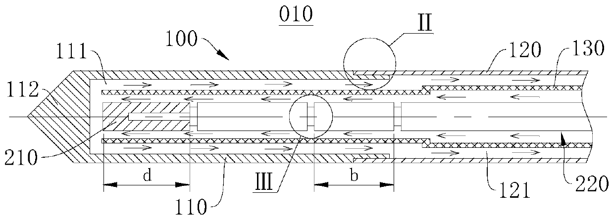
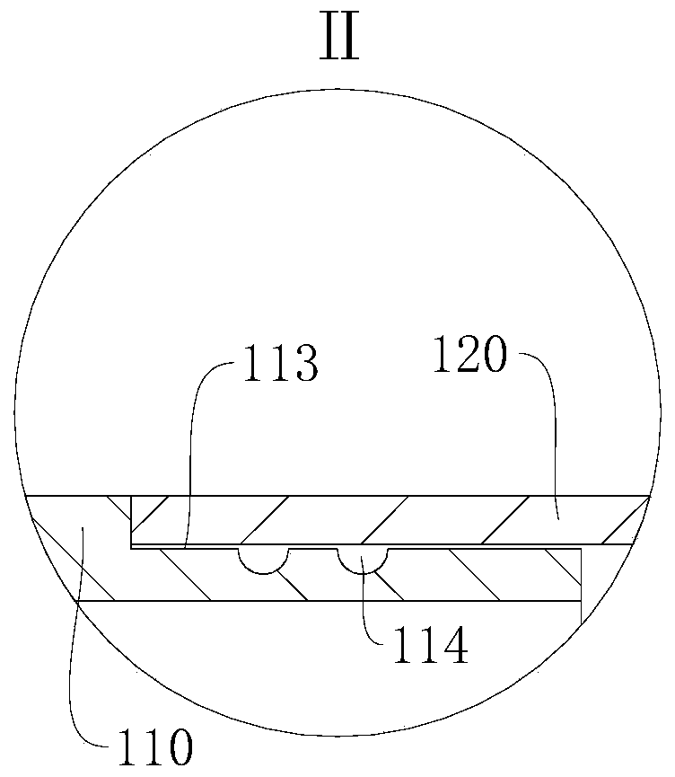
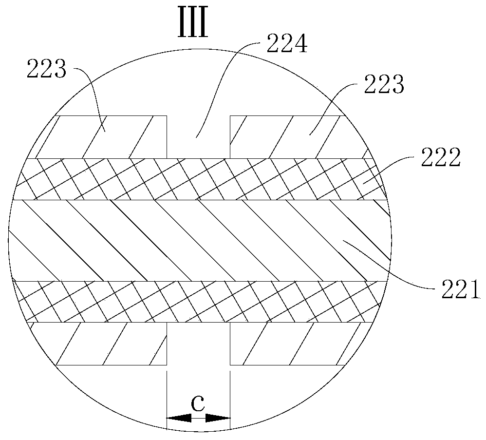
[0045] figure 1 A cross-sectional view of a partial structure of the microwave ablation needle 010 provided in this embodiment. Please refer to figure 1, this embodiment provides a microwave ablation needle 010 , which includes a microwave ablation needle body 100 , a microwave generating source and a coaxial cable 220 . The microwave ablation needle body 100 includes an insulating needle head 110 , a metal needle shaft 120 and an electrical isolation member. The insulating needle 110 is provided with a first accommodating cavity 111 , and the microwave generating source is disposed in the first accommodating cavity 111 . The metal needle bar 120 is provided with a second accommodation cavity 121 , and the coaxial cable 220 is passed through the second accommodation cavity 121 , and extends into the first accommodation cavity 111 to be electrically connected with the microwave generation source. The insulated needle 110 is connected to one end of the metal needle rod 120 , ...

Embodiment 2

[0071] This embodiment provides a microwave ablation method, which is implemented using the microwave ablation needle 010 provided in Embodiment 1, which includes the following steps:

[0072] Insert the insulated tip of the microwave ablation needle into the target tissue; electrically isolate the metal needle shaft from the coaxial cable.

[0073] When it is necessary to ablate the target tissue, the microwave ablation needle is punctured along the preset path until the insulated needle of the microwave ablation needle is inserted into the target tissue, and the microwave transmitted by the coaxial cable radiates outward through the metal column and the gap. The rod and the coaxial cable are electrically isolated through the cooling pipe, and the metal needle rod is floating. Therefore, in the process of radiating microwaves, the metal needle rod acts as a floating choke, which can suppress the microwave signal from traveling along the outer conductor of the coaxial cable to ...


PUM


Abstract

The invention relates to a microwave ablation needle body, a microwave ablation needle, and a microwave ablation method, which relate to the field of medical articles. The microwave ablation needle body comprises an insulating needle, a metal needle bar and an electrical separator. The insulating needle is provided with a first receiving cavity. A second receiving cavity is disposed in the metal needle bar, an insulating needle is connected to one end of the metal needle bar, and the first receiving cavity is in communication with the second receiving cavity. The electrical separator is disposed in the second receiving cavity for floating the metal needle bar. Since the metal needle bar is in a floating state, the metal needle bar can exert choking flow action and does not have a radiationfunction during microwave ablation, a microwave signal is suppressed from propagating in the direction of the microwave input, so that during the ablation process, the microwave signal radiates energy only through the insulating needle, which eliminates the tailing phenomenon in the traditional design and ensures the stability of the ablation form, and makes the needle closer to the sphere.

Description

technical field [0001] The invention relates to the technical field of medical supplies, in particular to a microwave ablation needle body, a microwave ablation needle and a microwave ablation method. Background technique [0002] In recent years, microwave ablation has become one of the important treatment methods for treating liver cancer, kidney cancer, thyroid and other soft tissues. Microwave ablation is to use antenna to radiate microwaves. Microwaves cause ions and polar water molecules in tissues to rotate, vibrate, and rub against each other to produce thermal effects, so that the treatment area can quickly reach a high temperature, and the tissues are coagulated, dehydrated and necrotic, so as to achieve the purpose of treatment. [0003] With the existing microwave ablation needles, the shape of the ablation area is unstable during microwave ablation, which is roughly ellipsoidal. In order to meet the treatment needs, the ablation area must be enlarged, which will...

Claims


Application Information

Patent Timeline
IPC IPC(8): A61B18/18
CPCA61B18/1815A61B2018/1869A61B2018/00577A61B2018/00023A61B2018/1853
Inventor 王卫中江荣华郑锐隆龙钦湘
Owner CANYON MEDICAL INC
Learn More