Supercharge Your Innovation With Domain-Expert AI Agents!

A leakage detection circuit

A leakage detection and circuit technology, which is applied in the field of current detection, can solve the problems that the circuit cannot work stably and the voltage decreases.

Active Publication Date: 2021-06-22
GIGADEVICE SEMICON (BEIJING) INC +1
View PDF10 Cites 0 Cited by
  • Summary
  • Abstract
  • Description
  • Claims
  • Application Information

AI Technical Summary

Problems solved by technology

When the circuit works normally, the voltage stabilizing capacitor C is charged to stabilize the voltage of the gate of the transistor M at Vg, and the charge stored in the stabilizing capacitor C is Q=C*Vg. However, if the voltage stabilizing capacitor C leaks, the voltage stabilizing capacitor C stores The charge of the transistor M decreases, the voltage of the gate of the transistor M decreases, and the circuit cannot work stably

Method used


Image

  • A leakage detection circuit
  • A leakage detection circuit
  • A leakage detection circuit

Examples


Embodiment 1

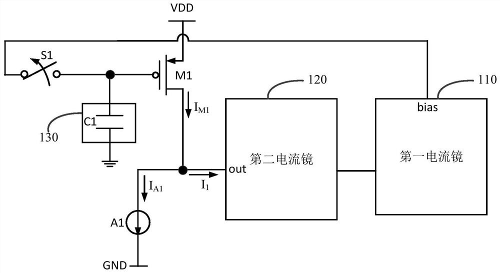
[0035] figure 2 For a circuit block diagram of a leakage detection circuit provided in Embodiment 1 of the present invention, see figure 2 , the leakage detection circuit includes a first current mirror 110, a second current mirror 120, a first transistor M1, a first switch S1 and a first reference current source A1;

[0036] The first current mirror 110 is connected to the second current mirror 120 for providing a reference current to the second current mirror 120;

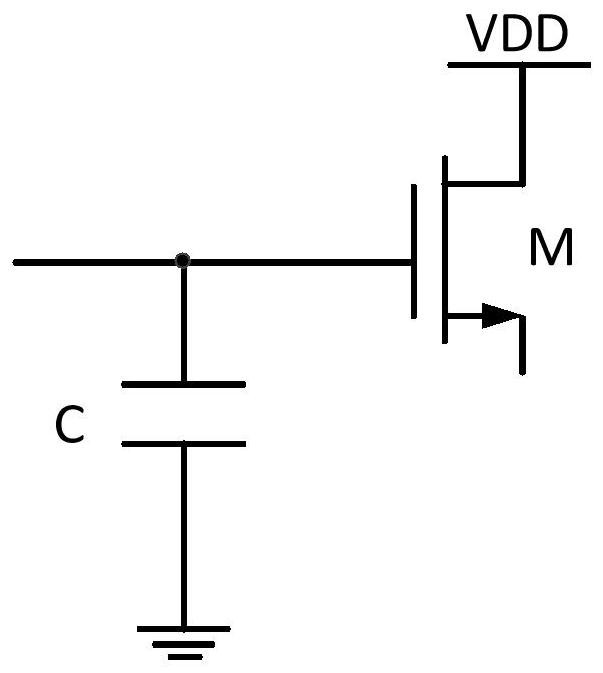
[0037] The first pole of the first transistor M1 is connected to the first power supply, the second pole of the first transistor M1 is connected to the current output terminal out of the second current mirror 120, and the gate of the first transistor M1 is connected to the first current through the first switch S1 The bias voltage terminal bias of the mirror 110 is connected; the gate of the first transistor M1 is used to connect with the element under test 130;

[0038] The first terminal of the first refere...

Embodiment 2

[0053] Figure 4 For a circuit block diagram of a leakage detection circuit provided in Embodiment 2 of the present invention, see Figure 4 , on the basis of the above embodiments, further, the leakage detection circuit can be selected as:

[0054] The first current mirror 110 includes a second transistor M2, a third transistor M3 and a second reference current source A2; the gate of the first transistor M1 is connected to the gate of the second transistor M2 through a first switch S1;

[0055] The first pole of the second transistor M2 is connected to the first power supply, the second pole of the second transistor M2 is connected to the bias voltage terminal of the second current mirror 120, the gate of the second transistor M2 is connected to the gate of the third transistor M3 connect;

[0056] The first pole of the third transistor M3 is connected to the first power supply, and the second pole of the third transistor M3 is connected to its gate;

[0057] The first end...


PUM


Abstract

The invention discloses a leakage detection circuit, which comprises a first current mirror, a second current mirror, a first transistor, a first switch and a first reference current source; the first current mirror is connected with the second current mirror, and is used to The two current mirrors provide the reference current; the first pole of the first transistor is connected to the first power supply, the second pole of the first transistor is connected to the current output end of the second current mirror, and the gate of the first transistor is connected to the first through the first switch. The bias voltage end of the current mirror is connected; the gate of the first transistor is used to be connected with the element to be tested; the first end of the first reference current source is connected with the current output end of the second current mirror, and the first end of the first reference current source The two terminals are connected with the second power supply. The embodiment of the present invention realizes the detection of the leakage current of the voltage stabilizing capacitor.

Description

technical field [0001] Embodiments of the present invention relate to current detection technology, and in particular to a leakage detection circuit. Background technique [0002] In the circuit system, the gate of the transistor usually needs to be connected with a voltage stabilizing capacitor to stabilize the gate voltage of the transistor and ensure the normal operation of the circuit. [0003] figure 1 It is the circuit block diagram of the voltage stabilizing capacitor circuit. When the circuit works normally, the voltage stabilizing capacitor C is charged to stabilize the voltage of the gate of the transistor M at Vg, and the charge stored in the stabilizing capacitor C is Q=C*Vg. However, if the voltage stabilizing capacitor C leaks, the voltage stabilizing capacitor C stores As the charge decreases, the voltage of the gate of the transistor M decreases, and the circuit cannot work stably. Therefore, it is necessary to detect the leakage current of the voltage sta...

Claims


Application Information

Patent Timeline
Patent Type & Authority Patents(China)
IPC IPC(8): G01R31/52
CPCG01R31/50
Inventor 方海彬张现聚刘铭
Owner GIGADEVICE SEMICON (BEIJING) INC
Features
  • R&D
  • Intellectual Property
  • Life Sciences
  • Materials
  • Tech Scout
  • Unparalleled Data Quality
  • Higher Quality Content
  • 60% Fewer Hallucinations
Learn More