
Unmanned aerial vehicle biomimetic obstacle avoidance control system and method based on LGMD

A control system and obstacle avoidance technology, applied in general control systems, control/regulation systems, adaptive control, etc., can solve problems such as obstacle materials, textures, and background complexity

Active Publication Date: 2019-07-02
LINGNAN NORMAL UNIV
View PDF5 Cites 3 Cited by
  • Summary
  • Abstract
  • Description
  • Claims
  • Application Information

AI Technical Summary

Problems solved by technology

[0003] In order to overcome the above-mentioned traditional UAV collision detection method, there are technical defects that rely on the complexity of obstacle materials, textures and backgrounds, and can only be used in simple and specific environments, and improve the flexibility of UAV obstacle avoidance and efficiency, providing a bionic obstacle avoidance control system for drones based on LGMD

Method used


Image

  • Unmanned aerial vehicle biomimetic obstacle avoidance control system and method based on LGMD
  • Unmanned aerial vehicle biomimetic obstacle avoidance control system and method based on LGMD
  • Unmanned aerial vehicle biomimetic obstacle avoidance control system and method based on LGMD

Examples


Embodiment 1

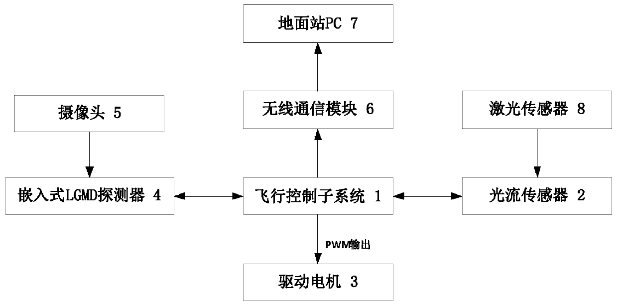
[0095] Such as figure 1 As shown, a UAV bionic obstacle avoidance control system based on LGMD, including flight control subsystem 1, optical flow sensor 2, drive motor 3, embedded LGMD detector 4, camera 5, wireless communication module 6 and ground station PC7; where:

[0096] Both the optical flow sensor 2 and the embedded LGMD detector 4 are electrically connected to the flight control subsystem 1 for information interaction;

[0097] Both the wireless communication module 6 and the drive motor 3 are electrically connected to the output end of the flight control subsystem 1;

[0098] The input terminal of the embedded LGMD detector 4 is signal-connected to the output terminal of the camera 5;

[0099] The wireless communication module 6 is wirelessly connected with the ground station PC7.

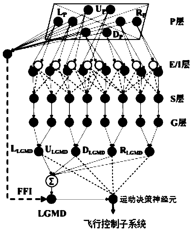
[0100] More specifically, the embedded LGMD detector 4 is provided with an LGMD neural network, and the video information collected by the camera 5 is calculated through the LGMD neu...

Embodiment 2

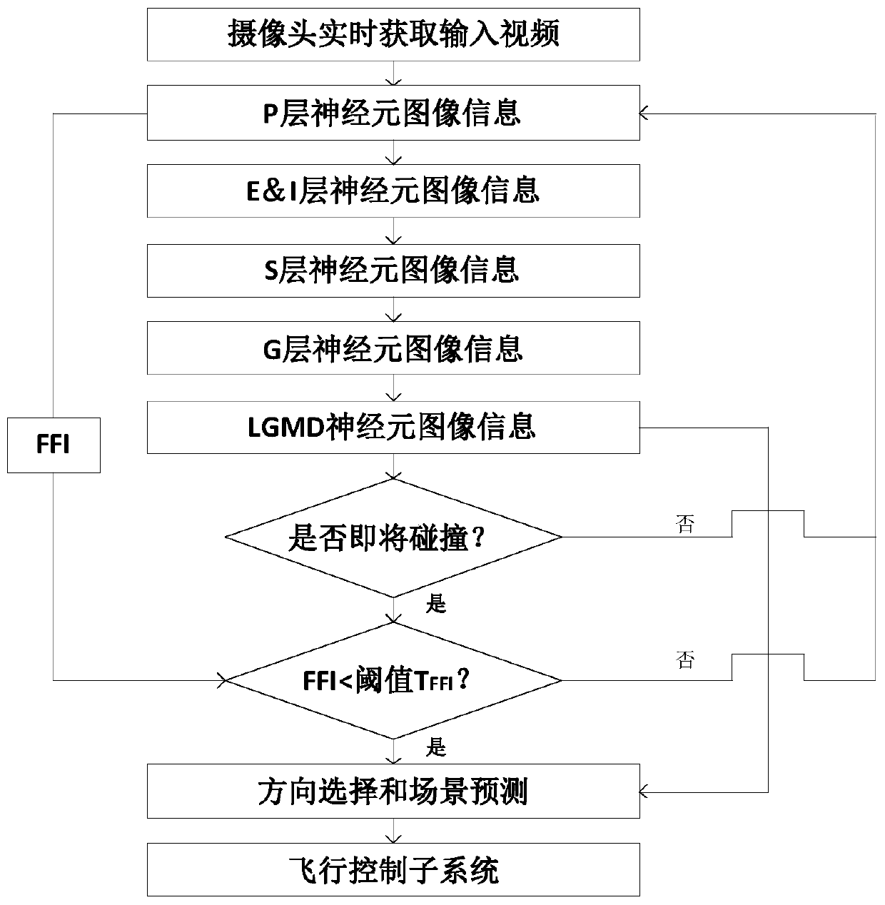
[0113] More specifically, on the basis of Embodiment 1, a bionic obstacle avoidance control method for UAV based on LGMD is provided, including the following steps:

[0114] S1: do real-time video collection through the camera 5, and get the input video;

[0115] S2: The embedded LGMD detector 4 obtains the field of view image information of the input video, calculates the obstacle avoidance control command through the LGMD neural network, and outputs it to the flight control subsystem 1 to realize the obstacle avoidance control of the UAV.

[0116] More specifically, such as image 3 As shown, the specific process of calculating the obstacle avoidance control instruction by the LGMD neural network is:

[0117] S21: P-layer neurons obtain the visual field image information of the input video, respond to the frame difference, and obtain the P-layer neuron membrane potential P f (x, y), specifically:

[0118] P f (x, y) = L f (x,y)-L f-1 (x, y); 1)

[0119] Among them: f ...


PUM


Abstract

The invention provides an unmanned aerial vehicle biomimetic obstacle avoidance control system based on LGMD. The system comprises a flight control subsystem, an optical flow sensor, a drive motor, anembedded LGMD detector, a camera, a wireless communication module and a ground station PC. The flow sensor and the embedded LGMD detector are electrically connected with the flight control subsystem.The wireless communication module and the drive motor are electrically connected with the output end of the flight control subsystem. The input end of the embedded LGMD detector is connected with theoutput end of the camera through signals. The wireless communication module is wirelessly connected with the ground station PC. The invention further provides an unmanned aerial vehicle biomimetic obstacle avoidance control method based on LGMD. By constructing an LGMD neural network and segmenting an image of field of view, spatial direction selection and scene prediction are realized during theflight of an unmanned aerial vehicle. The unmanned aerial vehicle can carry out real-time, efficient and obstacle avoidance flying in an unknown environment.

Description

technical field [0001] The present invention relates to the technical field of unmanned aerial vehicles, and more specifically, relates to a bionic obstacle avoidance control system for unmanned aerial vehicles based on LGMD, and also relates to a bionic obstacle avoidance control method for unmanned aerial vehicles based on LGMD. Background technique [0002] UAVs have broad application prospects in many scenarios such as geographic surveying, agricultural aviation, and danger detection, and safety has always been the focus of attention, especially in complex environments. Traditional UAVs use GPS and optical flow for path planning, combined with sensor detection methods such as ultrasonic, infrared, and laser for collision detection. However, such methods rely heavily on the complexity of obstacle materials, textures, and backgrounds , can only be used in simple and specific environments. In recent years, the obstacle avoidance method based on biological vision has become...

Claims


Application Information

Patent Timeline
Patent Type & Authority Applications(China)
IPC IPC(8): G05D1/10G05B13/02G05B13/04
CPCG05D1/101G05D1/0088G05B13/027G05B13/048G05B13/042
Inventor 马兴灶赵剑楠岳士岗
Owner LINGNAN NORMAL UNIV
Learn More