Airfoil profile with sharp leading edge, heavy camber, low Reynolds number and high lift drag ratio

A technology with low Reynolds number, high lift resistance and Reynolds number, applied in wing adjustment and other directions, can solve problems such as poor performance and low resistance, and achieve the effect of slow resistance change, reduced resistance, and reduced wetted area

Inactive Publication Date: 2019-07-05
CALCULATION AERODYNAMICS INST CHINA AERODYNAMICS RES & DEV CENT
View PDF6 Cites 3 Cited by
  • Summary
  • Abstract
  • Description
  • Claims
  • Application Information

AI Technical Summary

Problems solved by technology

[0005] The purpose of the present invention is to solve the problem of poor performance of conventional airfoils in low Reynolds number environments, to provide a low Reynolds number high lift-to-drag ratio airfoil with sharp leading edge and large camber, which not only conforms to the flow characteristics of low Reynolds number, but also has high lift Force, low drag characteristics, improving the efficiency of low Reynolds number aircraft

Method used


Image

  • Airfoil profile with sharp leading edge, heavy camber, low Reynolds number and high lift drag ratio
  • Airfoil profile with sharp leading edge, heavy camber, low Reynolds number and high lift drag ratio
  • Airfoil profile with sharp leading edge, heavy camber, low Reynolds number and high lift drag ratio

Examples


Embodiment Construction

[0019] The present invention will be described in further detail below through specific implementation examples and in conjunction with the accompanying drawings.

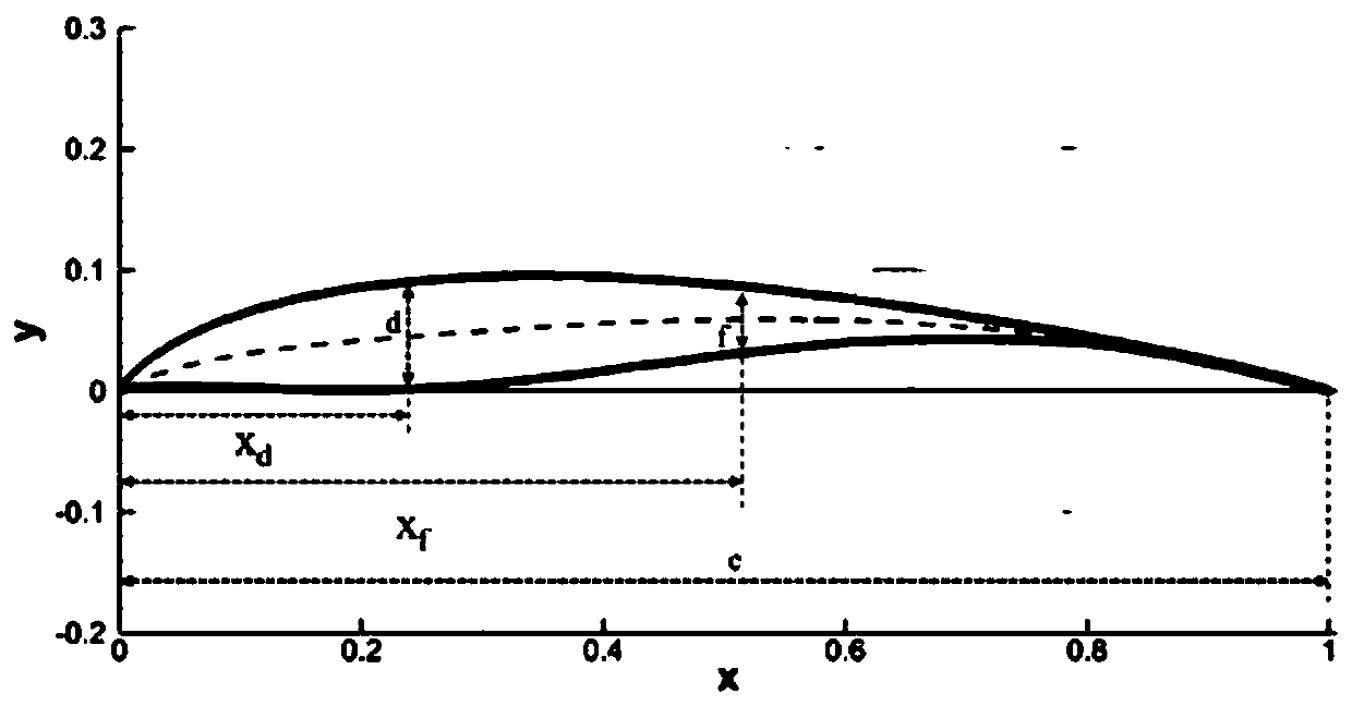
[0020] figure 1 Shown is a low Reynolds number high lift-drag ratio airfoil with sharp leading edge and large camber provided by the present invention, the maximum thickness of the airfoil is d / c=0.09, and the maximum thickness position is x d / c=0.274; the maximum camber of the airfoil is f / c=0.0595, and the maximum camber position is xf / c=0.527; wherein c is the chord length of the airfoil, d is the maximum thickness of the airfoil, and f is the maximum camber of the airfoil; The connection point of the upper and lower surfaces of the airfoil at the leading edge is the coordinate origin, and the axis where the chord length of the airfoil is located is the x-axis, and x d is the abscissa of the maximum thickness position, x f is the abscissa of the position of maximum curvature.

[0021] The upper surface and t...


PUM


Abstract

The invention discloses an airfoil profile with the sharp leading edge, heavy camber, low Reynolds number and high lift drag ratio, and relates to a low-Reynolds-number airfoil profile. According to the airfoil profile, the maximum thickness meets the relation of d / c=0.09, the maximum thickness position meets the relation of xd / c=0.274, the maximum camber meets the relation of f / c=0.0595, and themaximum camber position meets the relation of xf / c=0.527, wherein c is the chord length of the airfoil profile, d is the maximum thickness of the airfoil profile, and f is the maximum camber of the airfoil profile; and the connection point of the upper surface and the lower surface of the airfoil profile at the leading edge is the coordinate origin, the axis where the chord length of the airfoil profile is located is the x-axis, xd is the horizontal coordinate of the maximum thickness position, and xf is the horizontal coordinate of the maximum camber position. The airfoil profile abandons a blunt head shape of a conventional airfoil profile, and adopts the sharp leading edge, thus the wetting area is reduced, resistance is greatly reduced, and the lift coefficient of the airfoil profile is linearly changed before the stall; and meanwhile, the airfoil profile has the characteristic of heavy camber, a negative pressure area in the upper surface of the airfoil profile is generated through the heavy camber, and thus the characteristic of high lift is achieved.

Description

technical field [0001] The invention relates to a low Reynolds number airfoil, in particular to a low Reynolds number high lift-to-drag ratio airfoil with a sharp leading edge and large camber. Background technique [0002] The Reynolds number is used in aerodynamics to represent the ratio of air inertial force to viscous force, and the Reynolds number in the cruising state of large passenger aircraft and transport aircraft is on the order of tens of millions. Low Reynolds number flow (Reynolds number below 500,000) also widely exists, such as small wind turbines, micro aircraft, small unmanned aerial vehicles, near space vehicles, etc. However, the aerodynamic performance of airfoils is seriously affected by low Reynolds numbers, and airfoils that perform well at high Reynolds numbers tend to perform poorly at low Reynolds numbers. Under the low Reynolds number flow, the air is prone to separation and reattachment under the influence of the reverse pressure gradient, formi...

Claims


Application Information

Patent Timeline
Patent Type & Authority Applications(China)
IPC IPC(8): B64C3/44
CPCB64C3/44
Inventor 宋超李伟斌王子维李鹏
Owner CALCULATION AERODYNAMICS INST CHINA AERODYNAMICS RES & DEV CENT
Why Eureka
Try Eureka