Eureka AIR delivers breakthrough ideas for toughest innovation challenges, trusted by R&D personnel around the world.

Horizontal landing type multi-rotor unmanned aerial vehicle body box

A multi-rotor unmanned aerial vehicle, fuselage technology, applied in the fuselage, fuselage frame, unmanned aircraft and other directions, can solve the problems of scattered installation of airborne equipment, increase the weight of the structure, increase the weight of the cable, etc. Effectiveness of internal space utilization, simplified installation process, and shortened overall length

Pending Publication Date: 2018-09-07
天长市星舟航空技术有限公司
View PDF0 Cites 1 Cited by
  • Summary
  • Abstract
  • Description
  • Claims
  • Application Information

AI Technical Summary

Problems solved by technology

[0005] 1. At present, the shape of the power battery is cubic, and the utilization rate of the space in the spherical or arc-shaped fuselage is not high
[0006] 2. Due to the low utilization rate of the internal space of the fuselage, the installation of airborne equipment is scattered, and many cables are needed to connect the equipment, which increases the weight of the cables
[0007] 3. The fuselage adopts the overall force bearing method of the shell. In order to ensure the rigidity of the fuselage, the fuselage shell is very thick, which increases the structural weight
[0008] 4. In order to install airborne equipment, it is necessary to drill mounting holes on the fuselage shell, which destroys the force transmission route of the shell and reduces the structural strength
[0009] 5. The wetted area of ​​the circular fuselage is too large, which is easily disturbed by gusts of wind, which reduces the safety of the aircraft
[0011] 7. For some multi-rotor UAVs that require high levelness when landing, and some multi-rotor UAVs carry objects, the items loaded have higher requirements for levelness, while the existing multi-rotor UAVs During the landing process, due to different road conditions, the multi-rotor drone cannot land on the ground horizontally

Method used


Image

  • Horizontal landing type multi-rotor unmanned aerial vehicle body box
  • Horizontal landing type multi-rotor unmanned aerial vehicle body box
  • Horizontal landing type multi-rotor unmanned aerial vehicle body box

Examples


Embodiment 1

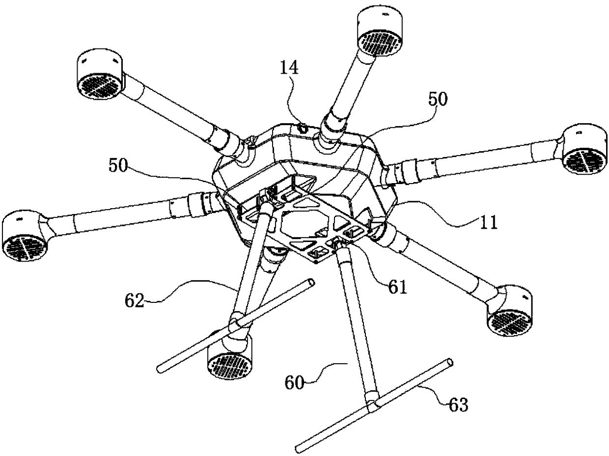
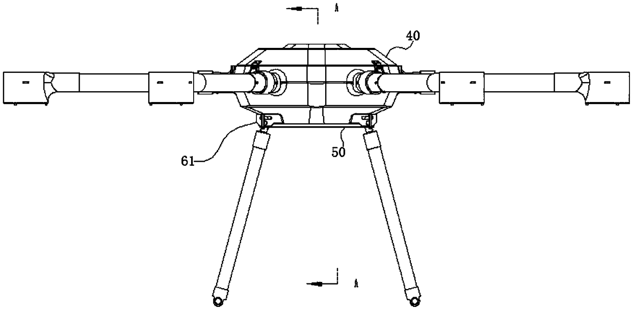
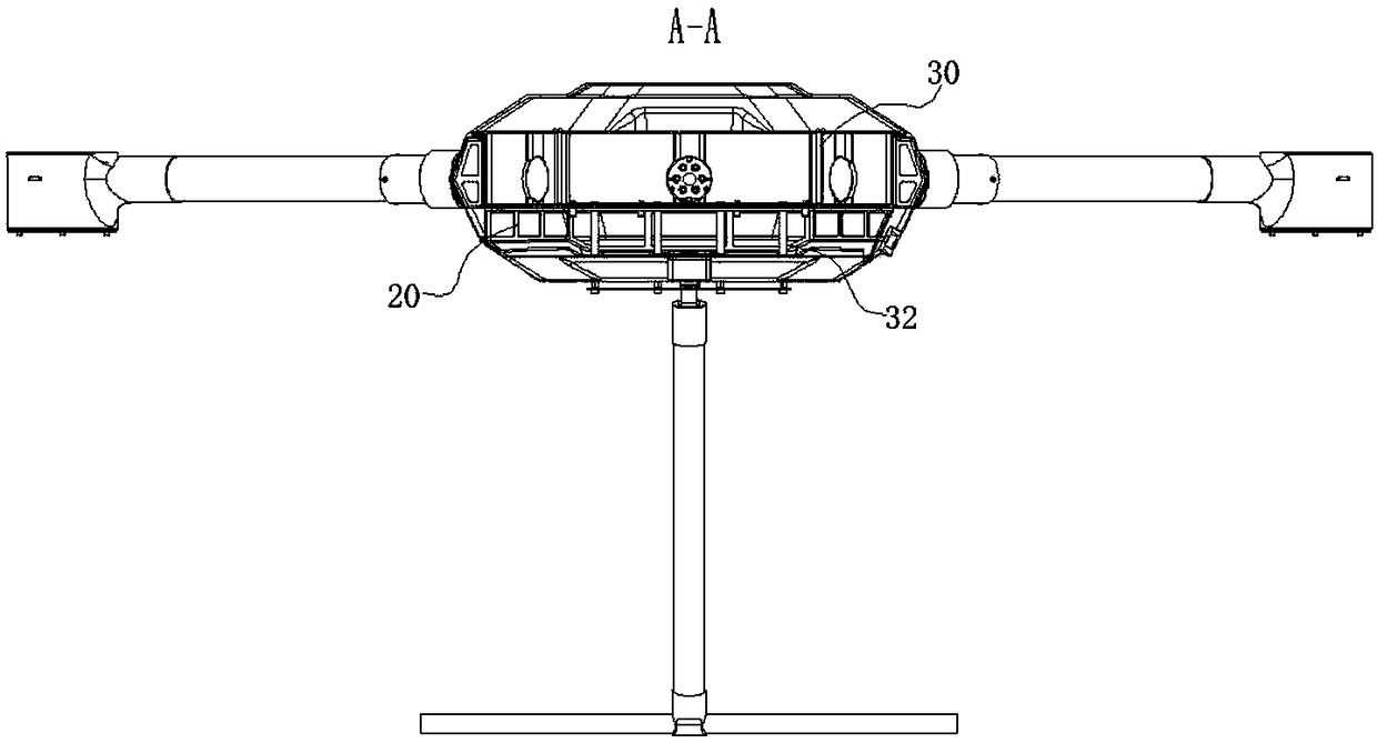
[0052] like Figure 1~3 and Figure 7 As shown, a fuselage box of a horizontal landing type multi-rotor UAV includes a polygonal fuselage shell 10, a fuselage bearing box 20 and a battery frame 30 are sequentially arranged in the fuselage shell 10, and the upper end of the fuselage shell 10 is also An upper cover 40 is provided, so that the design of the fuselage box of the UAV simplifies the main load-bearing components into a skin, a fuselage load-bearing box 20, and a battery frame 30, and the three parts are nested and glued sequentially. The traditional internal frame structure of the fuselage greatly simplifies the installation process and reduces the production cost.

[0053] like Figure 4 As shown, the fuselage shell 10 has a hexagonal structure, and the fuselage shell 10 includes a fuselage frame 11 and a skin, the skin covers the outer surface of the fuselage frame 11, and the lower end of the fuselage frame 11 protrudes inward to form a bearing bar 12. There are...

Embodiment 2

[0059] like Figure 9 , 10 11, the content of this embodiment is basically the same as that of Embodiment 1, and the similarities will not be repeated. The difference is that a horizontal landing system is also provided at the lower end of the landing gear, and the horizontal landing system includes an adaptive adjustment unit 70. Intervals are arranged at the lower end of the landing gear, and sliding terminals 71 can be slid up and down in the adaptive adjustment unit 70; the distance sensor module 80 for detecting the distance between the landing gear and the ground is arranged on the multi-rotor UAV; the drive unit 90, Arranged on the side of the adaptive adjustment unit 70, the drive unit 90 controls pressing and restricting / moving away from and releasing the sliding terminal 71 via the control module 91;

[0060] The control module 91, the drive unit 90 and the distance sensor module 80 are electrically connected; the distance sensor module 80 detects that the distance ...

Embodiment 3

[0065] like Figure 10 As shown, the content of this embodiment is basically the same as that of Embodiment 2, and the similarities will not be repeated. The difference is that the drive unit 90 includes an electric push rod arranged on one side of the limit plate 76, and the electric push rod The output end vertical limit plate 76 is arranged, and the control module 91 is electrically connected with the servo motor on the electric push rod. In this way, it is more convenient to control the electric push rod, and the electric push rod itself is a standard part, which is easier to purchase and replace. convenient.


PUM


Abstract

The invention relates to the technical field of multi-rotor unmanned aerial vehicles, in particular to a horizontal landing type multi-rotor unmanned aerial vehicle body box. The horizontal landing type multi-rotor unmanned aerial vehicle body box comprises a polygonal unmanned aerial vehicle body shell; an unmanned aerial vehicle body force bearing box and a battery frame are placed in the unmanned aerial vehicle body shell in sequence; an upper opening cover is also arranged at the upper end of the unmanned aerial vehicle body shell; therefore, a distance sensor module detects that the distance between a landing gear and the ground is less than or equal to a set value, each sliding terminal is in contact with the pavement under an effect of gravity and is rearranged in the vertical direction; each rearranged sliding terminal is matched with each concave-convex position on the pavement in a one-to-one corresponding manner; the distance sensor module transmits a detection signal to a control module; and the control module controls a driving unit to prop against and limit the sliding terminals so that the multi-rotor unmanned aerial vehicle lands in a horizontal state. The problem that the multi-rotor unmanned aerial vehicle cannot horizontally land due to complicated road condition in the prior art is solved.

Description

Technical field: [0001] The invention relates to the technical field of multi-rotor drones, in particular to a horizontal landing type multi-rotor drone fuselage box. Background technique: [0002] A multi-rotor UAV is a rotorcraft with more than two rotor axes. Rotated by electric motors at the end of each shaft, the rotors are driven to generate lift. The angle of the rotor is fixed rather than variable like in a helicopter. By changing the relative speed between different rotors, the propulsion torque can be changed, thereby controlling the trajectory of the aircraft. Because multi-rotors are relatively simple and stable, the current implementation of multi-rotor aircraft is much smaller than that of aircraft, so it is suitable for amateur use. Because multicopters are easy to manufacture and control, they are often used to make models and remote-controlled aircraft. The common ones are four-axis, six-axis, and eight-axis aircraft. It is small in size and light in we...

Claims


Application Information

Patent Timeline
Patent Type & Authority Applications(China)
IPC IPC(8): B64C1/06B64C25/24B64C25/26
CPCB64C1/068B64C25/24B64C25/26B64U50/19B64U10/10Y02T50/40
Inventor 胡铃心李金龙
Owner 天长市星舟航空技术有限公司
Why Eureka
Eureka Blog
Learn More