Fabricated roadbed construction system and technology suitable for deep soft foundation
A prefabricated and deep technology, applied in the direction of infrastructure engineering, roads, roads, etc., can solve the problems of large area, slow construction speed of subgrade on deep soft foundation, difficult to guarantee the quality of subgrade filling, etc., and achieve short construction period , Easy to assemble on site, light weight effect
- Summary
- Abstract
- Description
- Claims
- Application Information
AI Technical Summary
Problems solved by technology
Method used
Image
Examples
Embodiment 1
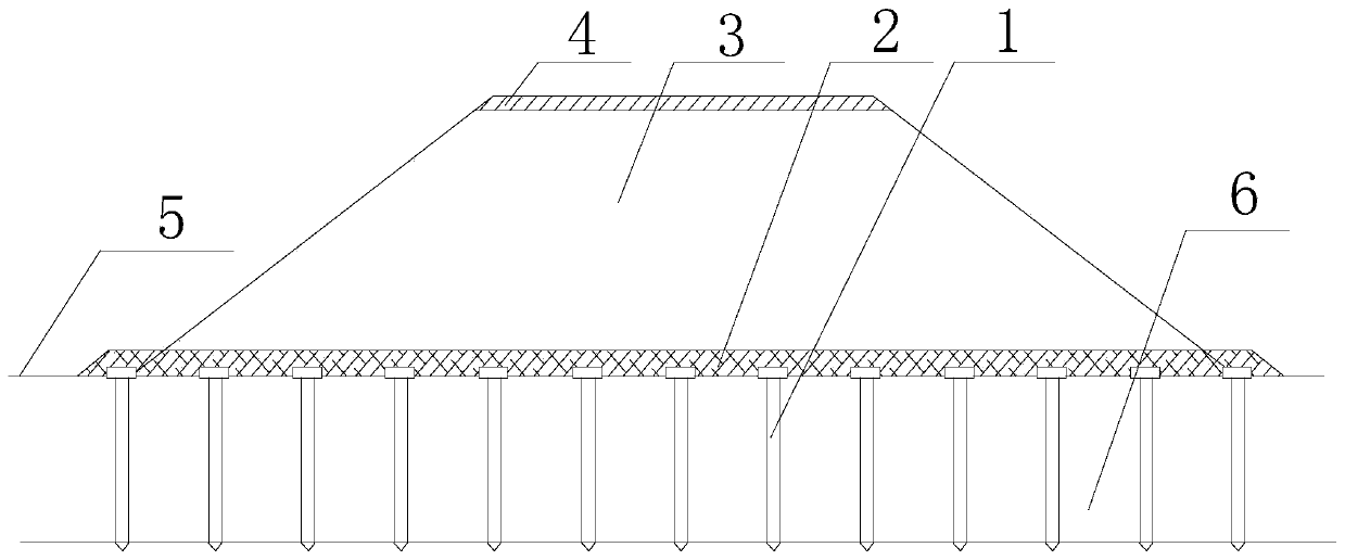
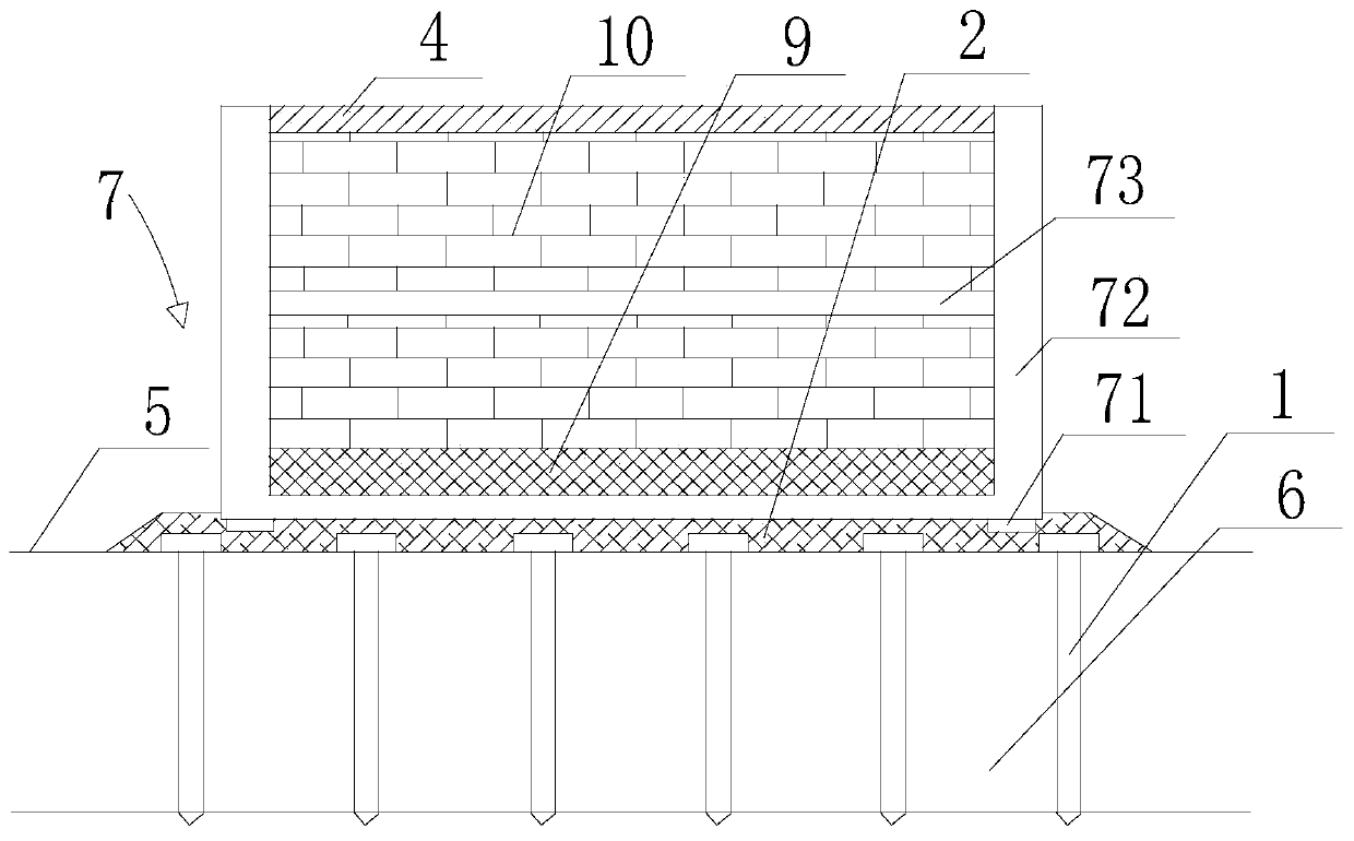
[0042] Such as Figure 2 to Figure 4As shown, a prefabricated subgrade construction system suitable for deep and thick soft foundations includes a ground line 5, a deep and thick soft base layer 6 below the ground line 5, a cushion 2 above the ground line 5, and the deep, thick soft base A number of prestressed pipe piles 1 are vertically inserted in the base layer 6, and an assembled support structure is detachably installed on the cushion layer 2, and the vertical direction of the assembled support structure is perpendicular to the cushion layer 2, specifically , the assembled retaining structure is a groove-shaped retaining wall 7, the groove-shaped retaining wall 7 includes a U-shaped groove 72, and the U-shaped groove 72 is detachably installed on the cushion layer 2, and the counterweight soil body 9 and the geotechnical foam blocks 10 are arranged between the two side walls of the U-shaped groove 72, and the bottom of the assembled retaining structure is laid with a cou...
Embodiment 2
[0044] Such as figure 2 As shown, this embodiment is based on Embodiment 1, the bottom of the U-shaped groove 72 is provided with a first insert 71, and the first insert 71 is embedded in the cushion layer 2; the two side walls of the U-shaped groove 72 The ends are connected by ribs 73 ; the ribs 73 are arranged in the middle of the U-shaped groove 72 in the vertical direction.
Embodiment 3
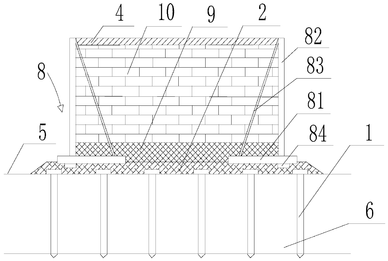
[0046] Such as image 3 , Figure 4 As shown, this embodiment is based on Embodiment 1, and the difference from Embodiment 1 is that the assembled retaining structure is a buttress-type structure, and the buttress-type structure includes two symmetrically arranged buttress-type retaining walls 8 , the buttress type retaining wall 8 includes a bottom plate 81, the upper end surface of the bottom plate 81 is vertically provided with a wall panel 82, and the upper end surface of the bottom plate 81 is symmetrically provided with two buttresses 83, and the buttresses 83 are A right-angled triangular plate, one right-angled side of the right-angled triangular plate is connected with the base plate 81, and the other right-angled side is connected with the wall panel 82, and the counterweight soil 9 and the geotechnical foam block 10 are filled between the two wall panels 82, And the buttress 83 is arranged on the outside of the counterweight soil 9 and the geotechnical foam block 1...
PUM
 Abstract
Description
Claims
Application Information
 - R&D
- Intellectual Property
- Life Sciences
- Materials
- Tech Scout
- Unparalleled Data Quality
- Higher Quality Content
- 60% Fewer Hallucinations
Browse by: Latest US Patents, China's latest patents, Technical Efficacy Thesaurus, Application Domain, Technology Topic, Popular Technical Reports.
© 2025 PatSnap. All rights reserved.Legal|Privacy policy|Modern Slavery Act Transparency Statement|Sitemap|About US| Contact US: help@patsnap.com


