Excavator oil tank

A technology for excavators and fuel tanks, applied in the field of excavator fuel tanks, can solve the problems of difficult to remove impurities, time-consuming and laborious, affecting the normal use of the engine, etc., and achieve the effect of convenient removal

Active Publication Date: 2019-07-05
浙江顺得机械有限公司
View PDF1 Cites 0 Cited by
  • Summary
  • Abstract
  • Description
  • Claims
  • Application Information

AI Technical Summary

Problems solved by technology

For China, which is in the period of accelerated urbanization development, the rapid infrastructure construction has created a demand for excavators. The variety and scope of application of excavators are becoming more and more extensive. Diesel is used to provide power. After a long period of use, there are many impurities deposited in the fuel tank. Since the diesel itself is relatively viscous, it is easy to produce sediment and block the oil circuit, making the excavator unable to work well for a long time. Therefore, the excavator The oil tank of the machine needs to be cleaned frequently
Otherwise, a large amount of precipitated impurities will enter the oil pipe when the excavator is working, which will accelerate the dirty clogging of the filter and the wear of precision coupling parts, thereby affecting the normal use of the engine
At present, the cleaning of the fuel tank is carried out by extending the spray head connected with the compressed air hose from the installation port of the fuel tank cap into the interior of the fuel tank. In order to clean the inside of the fuel tank, it is necessary to continuously change the spray during operation The position of the head, the whole cleaning process is time-consuming and laborious, and it is not easy to operate
[0003] The patent with the application number CN201610524097.5 discloses an easy-to-clean integrated excavator oil tank. The lower side of the side of the tank is respectively provided with oil outlets, and the bottom side of the tank is arc-shaped, although it is easy to make the tank The internal impurities settle to the oil outlet under the action of the arc-shaped bottom, but it is still difficult to remove some impurities that are firmly attached to the inner wall of the tank

Method used


Image

  • Excavator oil tank
  • Excavator oil tank
  • Excavator oil tank

Examples


Embodiment Construction

[0028] In the following, the present invention will be further described through specific embodiments in conjunction with the accompanying drawings.

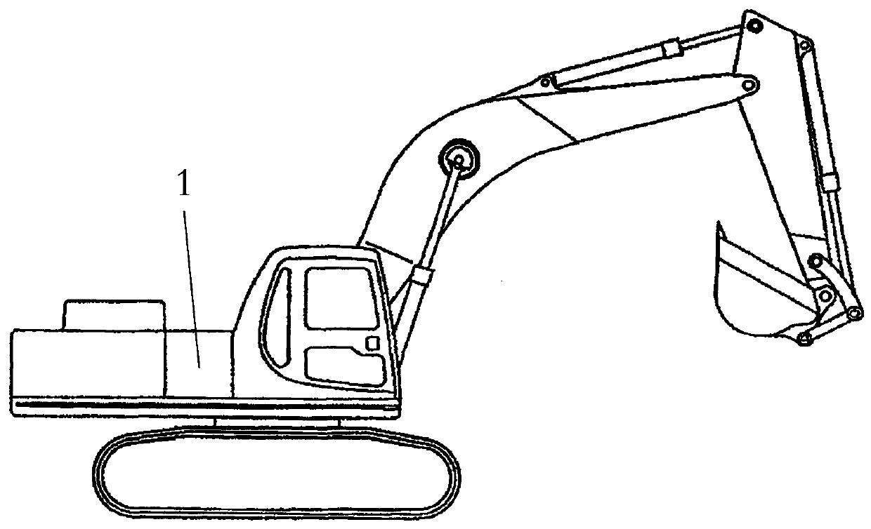
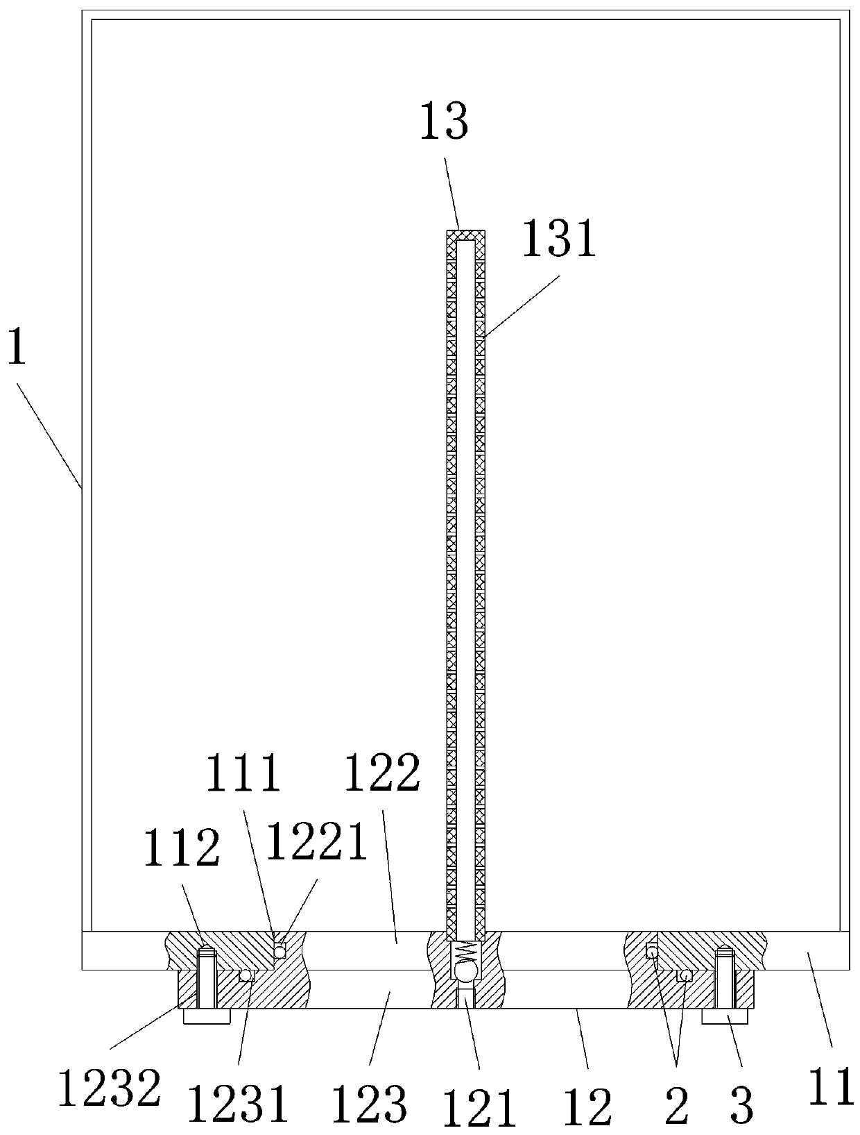
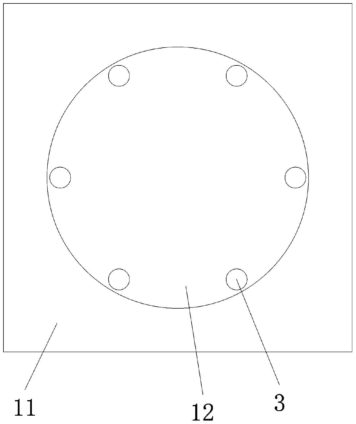
[0029] Such as figure 1 , figure 2 , image 3 , Figure 4 , An excavator oil tank. A fuel tank 1 is installed in the middle of the excavator. The bottom of the fuel tank 1 is closed by a peripheral sealing plate 11 and a middle sealing plate 12; the peripheral sealing plate 11 is welded to the side wall of the fuel tank 1, and there is a clean Through hole 111, the middle sealing plate 12 is installed at the cleaning through hole 111 to realize sealing; the middle part of the middle sealing plate 12 is provided with a vent hole 121 connected to the inside of the fuel tank 1. The vent hole 121 is located inside the fuel tank 1 and an air jet cleaning pipe is installed at one end 13.

[0030] Therefore, when the inside of the fuel tank needs to be cleaned, by ventilating the air jet cleaning pipe 13, the inner wall of the fuel tank 1...


PUM


Abstract

The invention provides an excavator oil tank. The oil tank is arranged at the middle part of an excavator; the bottom of the oil tank is sealed by a peripheral sealing plate and a middle sealing plate; the peripheral sealing plate is welded to the side wall of the oil tank, and a cleaning through hole is formed in the middle of the peripheral sealing plate; the middle sealing plate is arranged inthe cleaning through hole for realizing sealing; a vent hole communicating with the interior of the oil tank is formed in the middle part of the middle sealing plate; and an air injection cleaning pipe is arranged at one end, located inside the oil tank, of the vent hole. The peripheral sealing plate and the middle sealing plate are arranged at the bottom of the excavator oil tank; the middle sealing plate is provided with the vent hole and the air injection cleaning pipe which is arranged inside the tank and communicates with the vent hole. When the interior of the oil tank needs to be cleaned, the inner wall of the oil tank can be scoured and cleaned by aerating the air injection cleaning pipe; and the middle sealing plate can be disassembled to facilitate the complete removal of the impurities inside the oil tank.

Description

Technical field [0001] The invention relates to the field of excavator structures, and more specifically to an excavator oil tank. Background technique [0002] Excavators have become the king of construction machinery and are widely used in various occasions, including various harsh working conditions. For China, which is in a period of accelerating urbanization development, the booming infrastructure construction has given birth to the demand for excavators. The variety and application range of excavators are becoming more and more extensive. In the process of daily maintenance and repair, due to excavators Diesel is used to provide power. After a long period of use, the fuel tank will deposit more impurities. Because the diesel itself is relatively viscous, it is easy to precipitate and block the oil path, so that the excavator cannot work well for a long time, so digging The fuel tank of the machine must be cleaned frequently. Otherwise, a large amount of precipitated impur...

Claims


Application Information

Patent Timeline
Patent Type & Authority Applications(China)
IPC IPC(8): E02F9/08B08B9/093
CPCB08B9/0861B08B9/093E02F9/0883
Inventor 游迪王枫宇罗盛滔
Owner 浙江顺得机械有限公司
Why Eureka
Try Eureka