Surface cleaning system

A surface cleaning and surface cleaning device technology, applied in cleaning equipment, cleaning devices, cleaning machinery and other directions, can solve the problems of difficult to clean the ground, affect the cleaning effect, poor cleaning effect, etc., to strengthen the scraping cleaning path and improve the overall Effect of cleaning effect

Pending Publication Date: 2021-07-20
SHARKNINJA CHINA TECH CO LTD
View PDF0 Cites 0 Cited by
  • Summary
  • Abstract
  • Description
  • Claims
  • Application Information

AI Technical Summary

Problems solved by technology

However, after mopping the floor, the user needs to clean the mop manually, especially if the mop is not cleaned in time, it may cause the ground to be difficult to clean. The mop is even more annoying, and it needs to be manually replaced and cleaned back and forth, which also reduces the cleaning efficiency
[0003] In this regard, the applicant's prior patent application discloses a cleaning bucket used in conjunction with the mopping equipment. By fixing the surface cleaning device in the cleaning bucket, the rotating disk is used to drive the wiper on the cleaning piece. The rotation axis of the turntable is used as the rotation center to rotate and scrape for cleaning. However, in this cleaning method, the area of ​​the wiper near the center of rotation is relatively short due to the short rotation path, resulting in a relatively poor cleaning effect in this area compared to the outer area, which affects the overall cleaning. effect, there is still room for further improvement

Method used


Image

  • Surface cleaning system
  • Surface cleaning system
  • Surface cleaning system

Examples


Embodiment 1

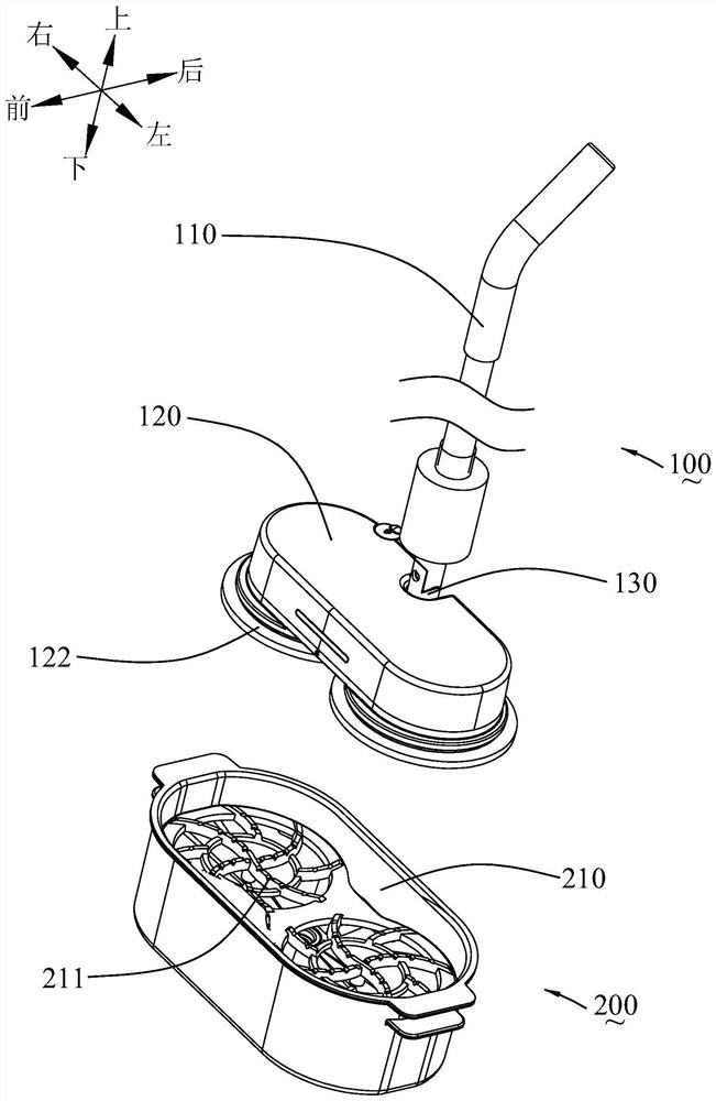
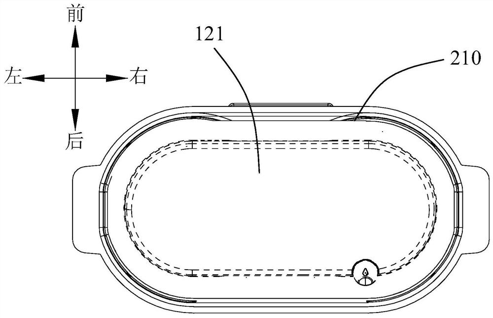
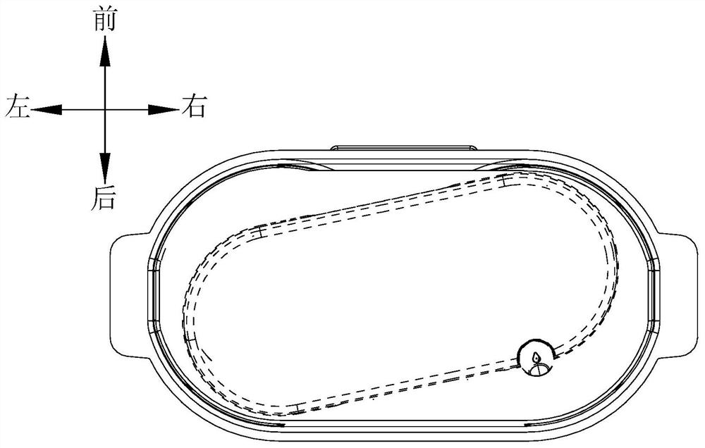
[0043] In this embodiment, the horizontal limiting member cooperates with the housing of the cleaning head 120 to make the cleaning head swing horizontally back and forth in the cleaning tank. Specifically, the housing 121 of the cleaning head includes a front side wall 121a and a rear side wall 121b, and the cleaning tank 210 includes a front side wall 210a and a rear side wall 210b.

[0044] In this way, the matching position of the horizontal limiter and the housing is relatively higher than the scraping surface of the wiper and the cleaning member, preventing the cleaning head from detaching from the cleaning tank, so that the cleaning head is more stable when it swings horizontally in the cleaning tank ,

[0045] In an implementation manner of this embodiment, the horizontal limiting member is a side wall of a cleaning tank. Since the side wall of the cleaning tank defines the cleaning space in the cleaning tank, by setting the side wall of the cleaning tank as a horizon...

Embodiment 2

[0058] combined with Figure 8 , 9 As shown, the difference between this embodiment and Embodiment 1 is that: the horizontal limiting member cooperates with the turntable to make the cleaning head reciprocate horizontally in the cleaning tank.

[0059] Preferably, the horizontal limiting member is a limiting column 211a, which is arranged on the cleaning member 211 and there are two in number, and the bottom of the turntable 122 is provided with a limiting column corresponding to the limiting column 211a. Groove (not shown in the figure), when the surface cleaning device is placed in the cleaning tank, the limiting post extends into the limiting groove for cooperation, so that the cleaning head swings horizontally back and forth in the cleaning tank.

Embodiment 3

[0061] The difference between this embodiment and Embodiments 1 and 2 is that the cleaning assembly in this embodiment also includes a rotatable valve stem 230, the valve stem 230 is at least partly arranged in the cleaning tank, and the valve stem 230 includes a driving end 231 and driven end 232, the bottom of the cleaning chamber is provided with a sewage outlet 213, the driven end 232 of the valve stem 230 is provided with a valve body for closing the sewage outlet 213, the driving end 231 of the valve stem 230 is in contact with the mop, and the turntable turns When rotating, the mop drives the valve rod 230 to rotate to open the sewage outlet 213 . Specifically, in this embodiment, the turntable on the left side of the cleaning head is set corresponding to the valve stem 230, and when the turntable on the left side of the cleaning head is reversed, the mop drives the valve stem 230 to rotate to open the sewage outlet 213, When the turntable on the left side of the cleani...


PUM


Abstract

The invention relates to a surface cleaning system which comprises a surface cleaning device with a cleaning head and a cleaning assembly used for cleaning the surface cleaning device, two rotatable rotating discs distributed left and right are arranged at the bottom of the cleaning head, wiping pieces are arranged on the rotating discs, and a driving assembly for driving the rotating discs to rotate is arranged in the cleaning head, the cleaning assembly comprises a cleaning groove, a cleaning part and cleaning liquid are arranged in the cleaning groove, the cleaning head is placed in the cleaning groove, the wiping part abuts against the cleaning part, the cleaning groove is provided with a horizontal limiting part, the driving assembly drives the wiping part to rotate on the cleaning part, and the horizontal limiting part is matched with the cleaning head, and the cleaning head horizontally swings back and forth in the cleaning tank. By the adoption of the technical scheme, when the rotating disc drives the wiping piece to conduct scraping cleaning, certain slippage is generated in the horizontal direction or the radial direction of the rotating disc, and circumferential rotating cleaning and horizontal slippage cleaning are combined to enhance cleaning of the area, close to the rotating center, of the cleaning wiping piece.

Description

technical field [0001] The invention relates to the field of household cleaning appliances, in particular to a surface cleaning system for cleaning. Background technique [0002] The floor mopping equipment currently on the market usually adopts a turntable structure, specifically, a turntable arranged side by side is arranged at the bottom of the cleaning head, and a mop in a similar shape that is in contact with the surface to be cleaned is provided on the turntable. However, after mopping the floor, the user needs to clean the mop manually, especially if the mop is not cleaned in time, it may cause the ground to be difficult to clean. The mop is even more annoying, and it needs to be manually replaced and cleaned back and forth, which also reduces the cleaning efficiency. [0003] In this regard, the applicant's prior patent application discloses a cleaning bucket used in conjunction with the mopping equipment. By fixing the surface cleaning device in the cleaning bucket...

Claims


Application Information

Patent Timeline
IPC IPC(8): A47L11/283A47L11/40
CPCA47L11/283A47L11/40A47L11/4038A47L2201/028
Inventor 王旭宁周伟岑明崔卫民
Owner SHARKNINJA CHINA TECH CO LTD
Why Eureka
Try Eureka