Heating washing device used for toilet

A technology for utensils and toilets, applied in the field of sanitation facilities, can solve problems such as electricity safety, residual washing liquid, and low heating efficiency, and achieve the effects of ensuring safe use, improving safety performance, and low cost

Pending Publication Date: 2019-07-05
中山市国安环保设备有限公司
View PDF0 Cites 0 Cited by
  • Summary
  • Abstract
  • Description
  • Claims
  • Application Information

AI Technical Summary

Problems solved by technology

[0002] Existing sanitation facilities, such as smart toilets, have the function of cleaning the user's buttocks on the toilet. However, it is not easy to retrofit and add this function to the old toilet. At the same time, there are still many problems in this type of heating and cleaning appliances, such as , in addition to simply heating the water to realize the cleaning function, you can also add washing liquid, but in the existing structure, the washing liquid is artificially squeezed out to smear and clean. It is not convenient for users to use, and secondly, users cannot accurately control the dosage, resulting in a lot of washing liquid remaining on the human body in the end, and it takes a lot of time for users to rinse
[0003] In addition, there is also the issue of electricity safety. Since the water flows directly to the human body after heating the water, safety issues must be paid attention to so that there will be no danger when the current passes through the water and the human body.
[0004] In addition, the problem of heating efficiency also needs to be considered. The existing rod-type heating body has low heating efficiency.

Method used


Image

  • Heating washing device used for toilet
  • Heating washing device used for toilet
  • Heating washing device used for toilet

Examples


Embodiment Construction

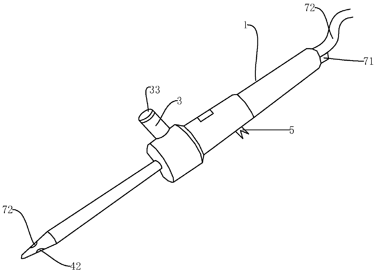
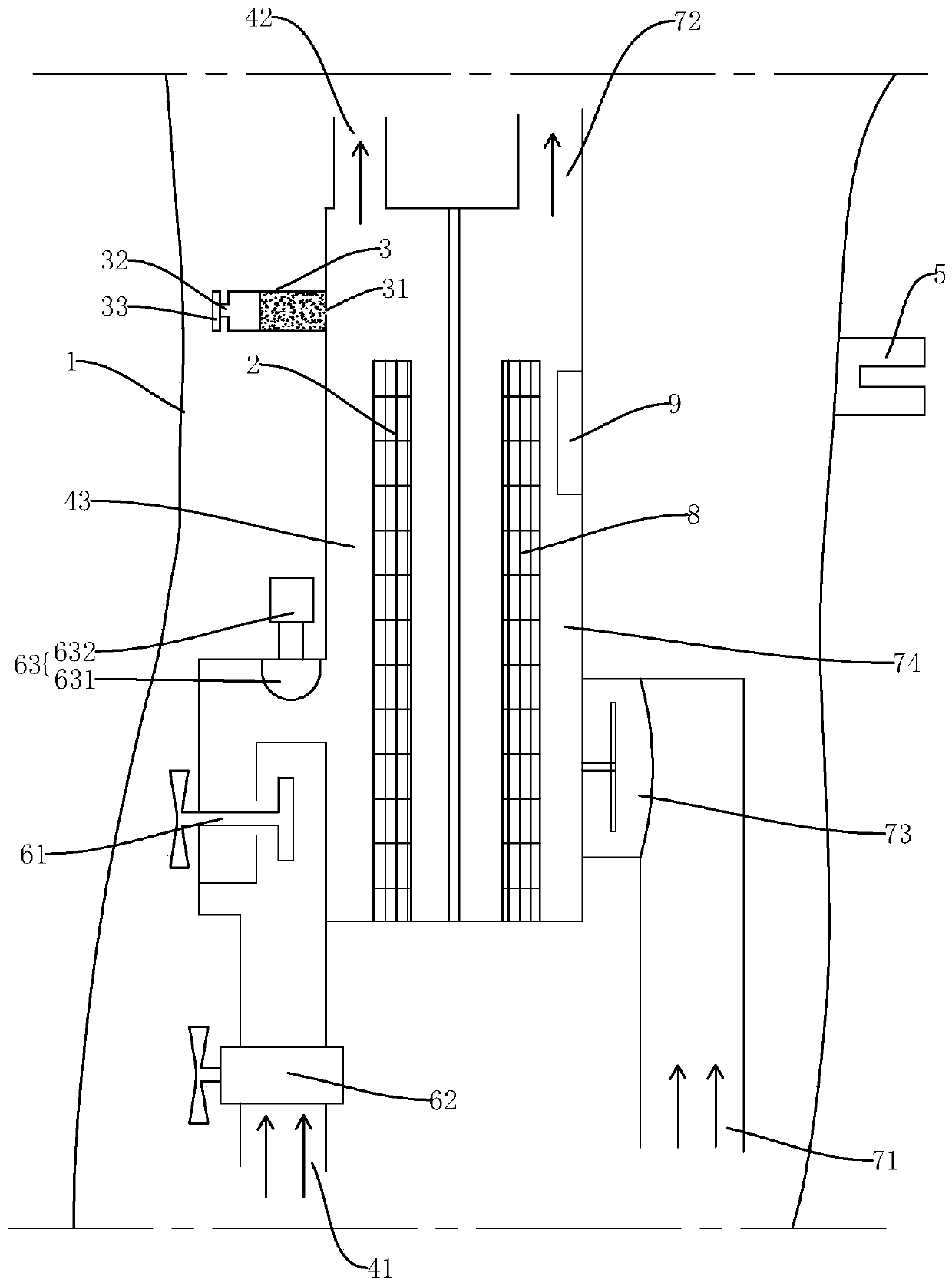
[0031] like Figure 1-Figure 4 As shown, a heating and cleaning appliance for a toilet includes a housing 1, a first heating component 2, and a liquid storage cavity 3. The specific shape of the housing 1 is not limited here, and it can preferably be similar to a commonly used shower head, and A handle is provided on the surface of the housing 1 , and a heat insulating material, such as heat insulating silica gel, etc. may be provided on the surface of the housing 1 to improve the user's comfort during use.

[0032] The housing 1 is provided with a water inlet 41 that can communicate with an external water supply source, a water outlet 42 that outputs water, and a water delivery inner chamber 43 that communicates with the water inlet 41 and the water outlet 42 respectively;

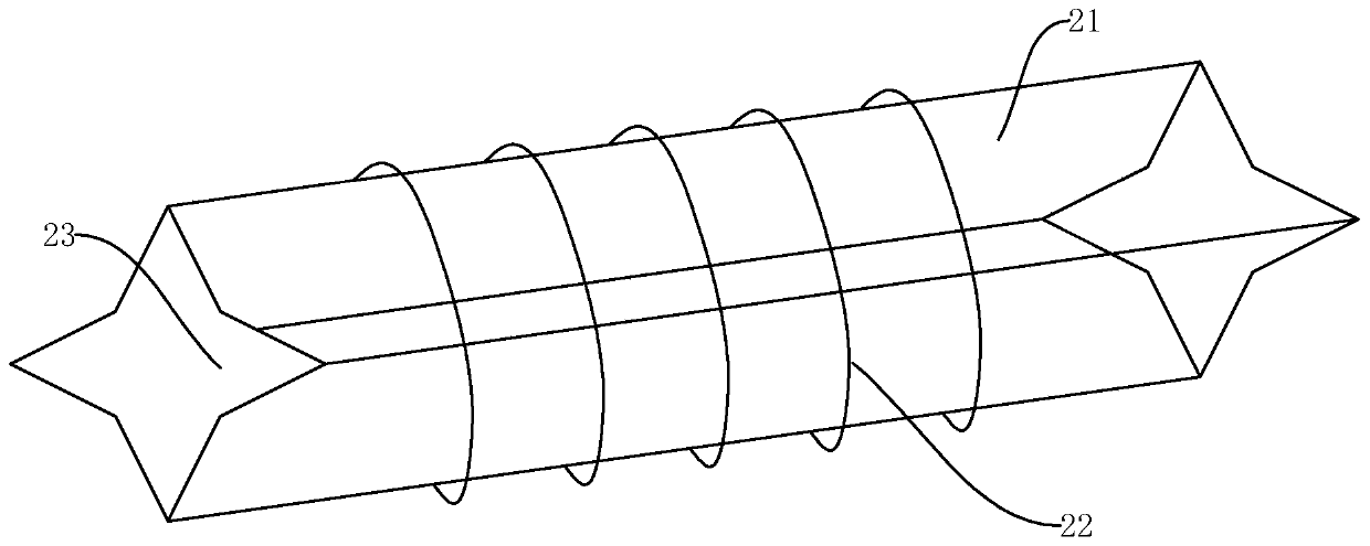
[0033] The first heating component 2 is arranged in the water delivery cavity 43 to heat the water body to be delivered;

[0034] The liquid storage chamber 3 can store washing liquid and air. The liquid...


PUM


Abstract

The invention discloses a heating washing device used for a toilet. The heating washing device comprises a shell, a first heating part and a liquid storing cavity, wherein the shell is provided with awater inlet end capable of communicating an external water supply source, a water outlet end for delivering out a water body, and a water delivering inner cavity communicating with the water inlet end and the water outlet end; the first heating part is arranged in the water delivering inner cavity for heating the conveyed water body; and the liquid storing cavity can store a scrubbing solution and air, liquid outlet holes are arranged in the liquid storing cavity, the liquid storing cavity is arranged in the shell, and meanwhile, heat emitted by the first heating part can be conducted to theliquid storing cavity, so that after air in the liquid storing cavity expands due to heating, the scrubbing solution is driven to enter the water delivering inner cavity from the liquid outlet holes.According to the design, the principle of thermal expansion and cold shrinkage of air is ingeniously utilized, when the heating washing device heats the outlet water for realizing washing, an appropriate amount of scrubbing solution can be mixed, the man-made operation is not needed, thus the problem that due to the improper use amount of the user, the scrubbing solution needs to be removed by consuming abundant time is solved, and therefore, the use of the user is facilitated.

Description

technical field [0001] The invention relates to the field of sanitation facilities, in particular to cleaning appliances for toilets. Background technique [0002] Existing sanitation facilities, such as smart toilets, have the function of cleaning the user's buttocks on the toilet. However, it is not easy to retrofit and add this function to the old toilet. At the same time, there are still many problems in this type of heating and cleaning appliances, such as , in addition to simply heating the water to realize the cleaning function, you can also add washing liquid, but in the existing structure, the washing liquid is artificially squeezed out for smearing and cleaning. It is not convenient for the user to use, and secondly, the user cannot accurately control the dosage, resulting in a lot of washing liquid remaining on the human body in the end, and it takes a lot of time for the user to rinse. [0003] In addition, there is also the issue of electricity safety. Since th...

Claims


Application Information

Patent Timeline
Patent Type & Authority Applications(China)
IPC IPC(8): E03D9/08E03D9/03F24H1/20F24H9/18F24H9/20F26B21/00
CPCE03D9/03E03D9/031E03D9/08E03D2009/028F24H1/202F24H9/1818F24H9/2021F24H2250/02F26B21/004
Inventor 晏光明
Owner 中山市国安环保设备有限公司
Why Eureka
Try Eureka