Double-valve-seat regulating ball valve

A technology of regulating ball and double valve seat, which is applied in the field of regulating valves, can solve the problems of large rotating torque of the valve stem and wear of the valve core of the ball valve, and achieve the effect of reducing the rotating torque, reducing friction and improving the adjustment accuracy

Inactive Publication Date: 2019-07-05
NUCLEAR POWER INSTITUTE OF CHINA
View PDF8 Cites 1 Cited by
  • Summary
  • Abstract
  • Description
  • Claims
  • Application Information

AI Technical Summary

Problems solved by technology

[0005] The purpose of the present invention is to provide a double-seat regulating ball valve to solve the problems of rapid wear of the ball valve spool and large rotating torque of the valve stem in the prior art, to improve the two-way sealing performance of the ball valve, improve the adjustment accuracy, and reduce the valve core. Purpose of wear and turning torque

Method used


Image

  • Double-valve-seat regulating ball valve
  • Double-valve-seat regulating ball valve
  • Double-valve-seat regulating ball valve

Examples


Embodiment 1

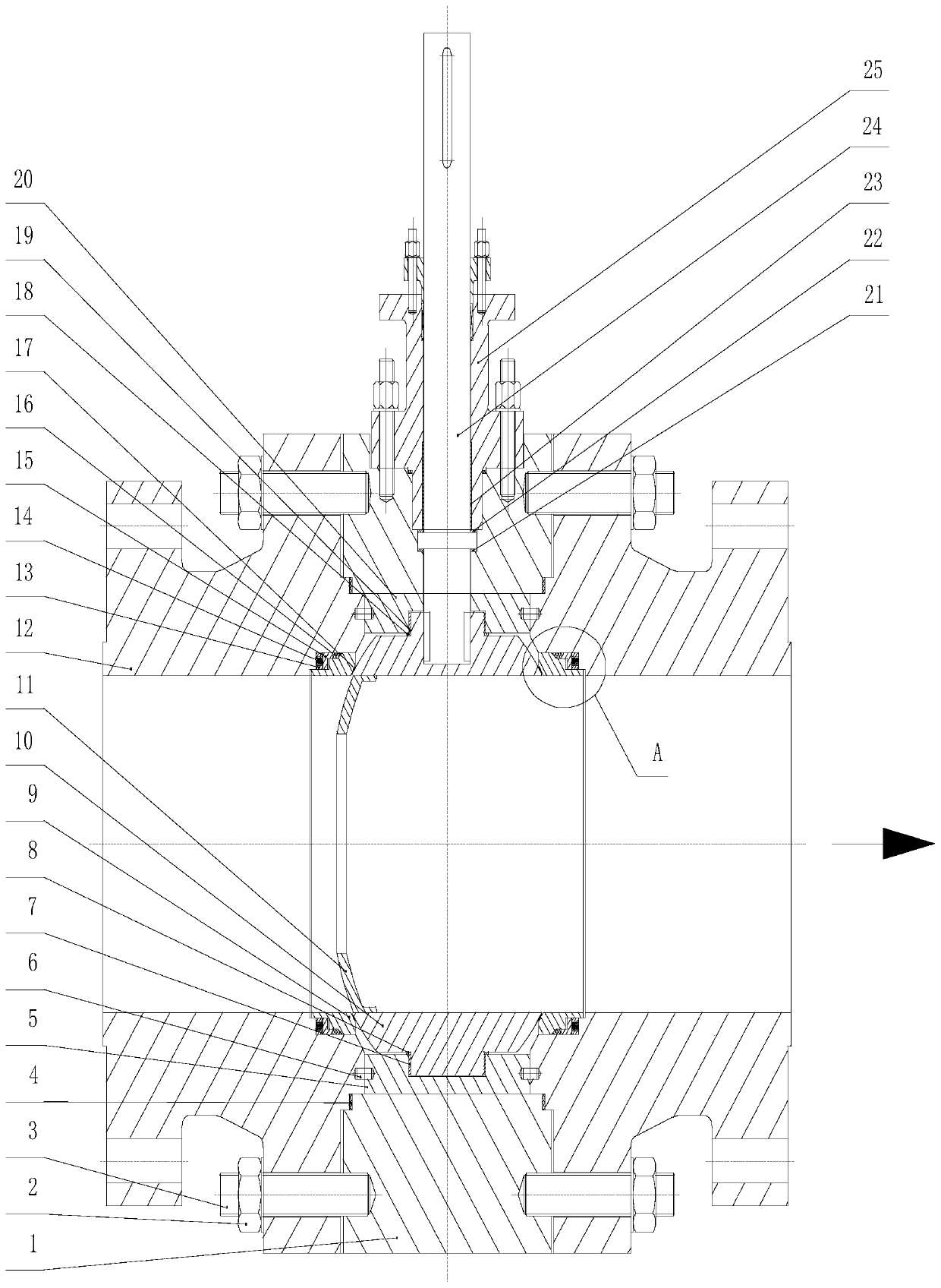
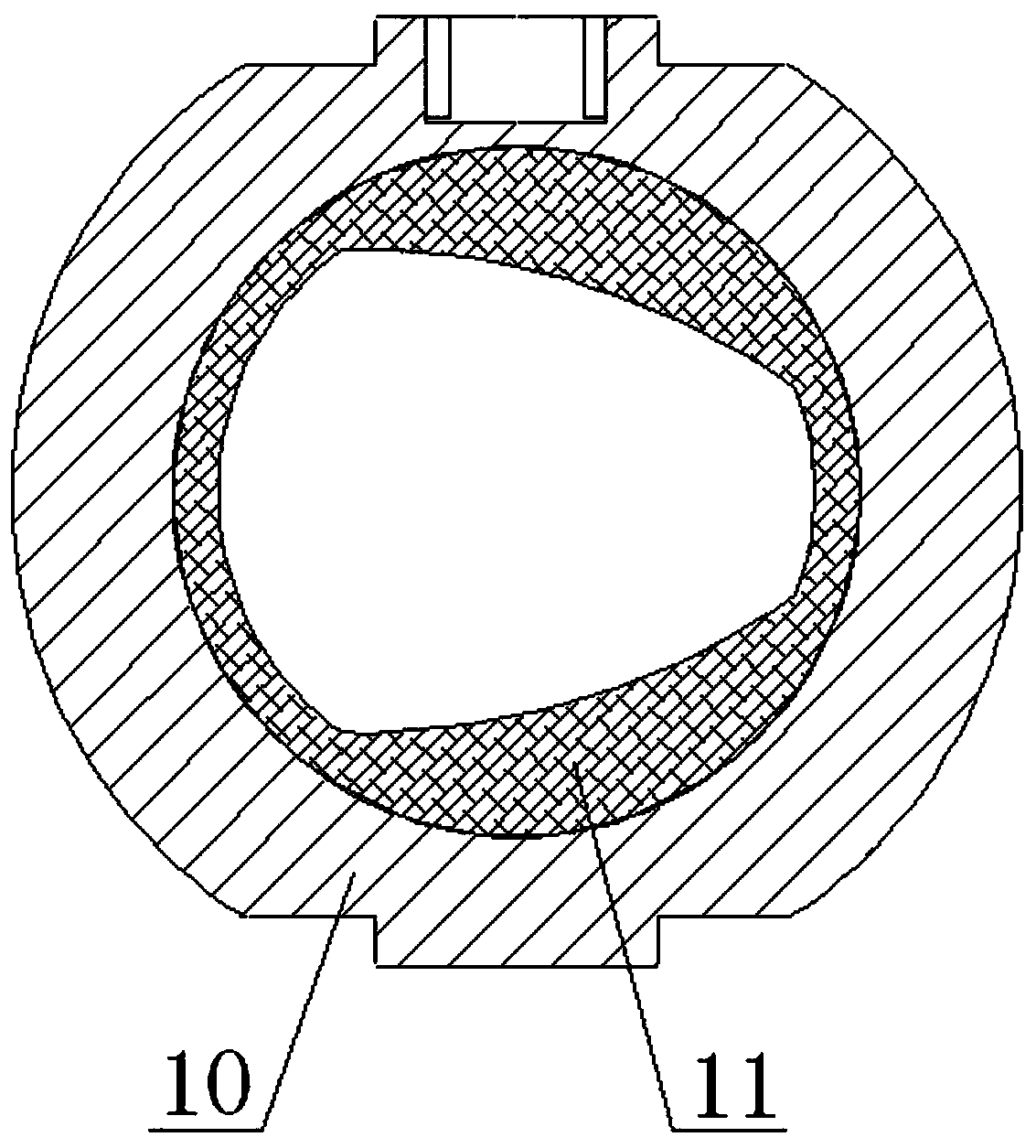
[0029] Such as figure 1 and figure 2 A double-seat regulating ball valve shown includes a valve body, a valve seat, and a valve core. The valve body includes a main valve body 1 and two auxiliary valve bodies 12 respectively fixed on both sides of the main valve body 1; There are two valve seats 9, the valve seats 9 are located between the two auxiliary valve bodies 12, and the two valve seats 9 are located on opposite sides of the valve body in the radial direction; the valve core is located between the two valve seats 9. This embodiment adopts a double valve seat structure, which is suitable for high temperature, high pressure and frequently changing working conditions. It can avoid valve locking caused by deformation of valve trim under high temperature and high pressure working conditions, and significantly improve the two-way sealing performance of the valve.

Embodiment 2

[0031] Such as Figure 1 to Figure 3A double-seat regulating ball valve shown includes a valve body, a valve seat, and a valve core. The valve body includes a main valve body 1 and two auxiliary valve bodies 12 respectively fixed on both sides of the main valve body 1; There are two valve seats 9, the valve seats 9 are located between the two auxiliary valve bodies 12, and the two valve seats 9 are located on opposite sides of the valve body in the radial direction; the valve core is located between the two valve seats 9.

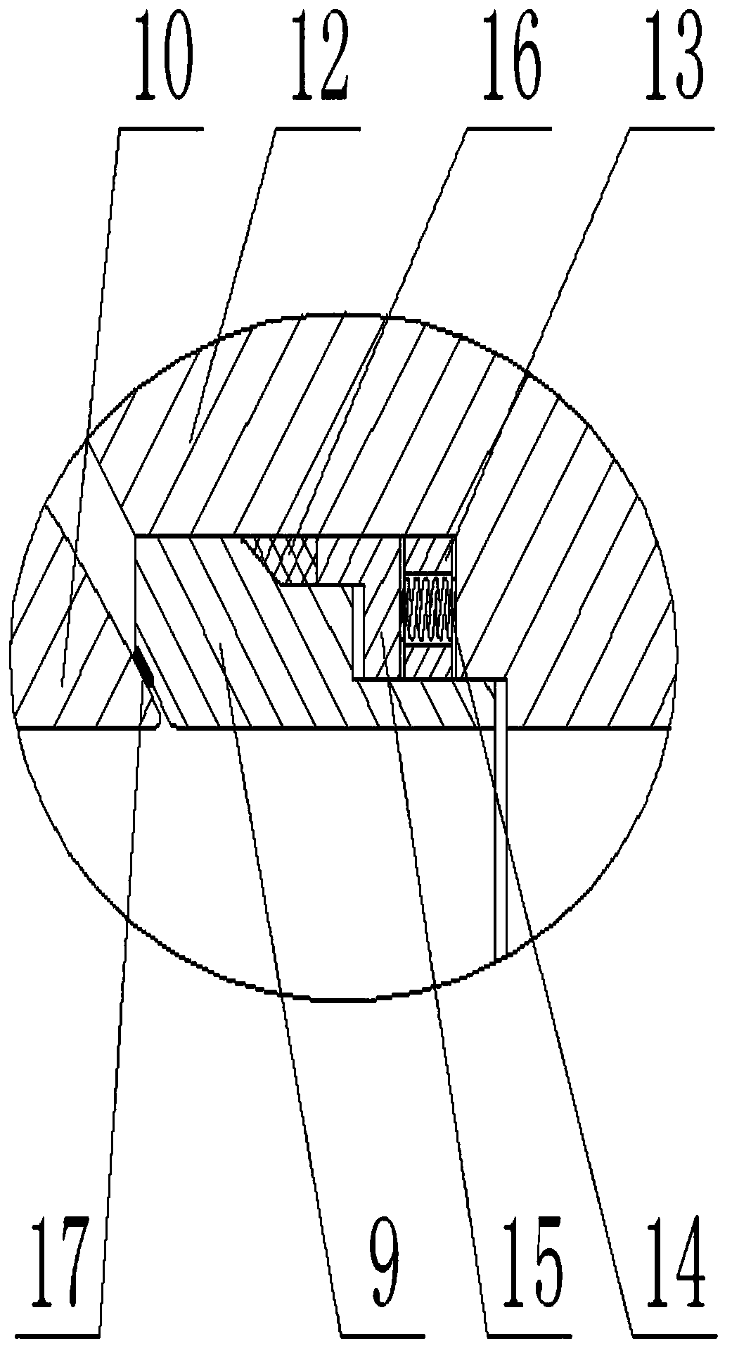
[0032] The main valve body 1 and the auxiliary valve body 12 are fixedly connected by bolts 3 , and a sealing gasket 4 is arranged between the main valve body 1 and the auxiliary valve body 12 . The valve seat 9 is installed in the auxiliary valve body 12 through the valve seat bracket 15; several groups of springs 14 are evenly distributed along the circumferential direction between the valve seat 9 and the auxiliary valve body 12, and the two ends of the ...

Embodiment 3

[0040] Such as Figure 1 to Figure 3 A double-seat regulating ball valve shown includes a valve body, a valve seat, and a valve core. The valve body includes a main valve body 1 and two auxiliary valve bodies 12 respectively fixed on both sides of the main valve body 1;

[0041] There are two valve seats 9, the valve seat 9 is located between the two auxiliary valve bodies 12, and the two valve seats 9 are located on opposite sides in the radial direction of the valve body; the valve core is located between the two valve seats 9 between. The main valve body 1 and the auxiliary valve body 12 are fixedly connected by bolts 3 , and a sealing gasket 4 is arranged between the main valve body 1 and the auxiliary valve body 12 . The valve seat 9 is installed in the auxiliary valve body 12 through the valve seat bracket 15; several groups of springs 14 are evenly distributed along the circumferential direction between the valve seat 9 and the auxiliary valve body 12, and the two ends...


PUM


Abstract

The invention discloses a double-valve-seat regulating ball valve comprising a valve body, valve seats and a valve element. The valve body comprises a main valve body and two auxiliary valve bodies fixed to the two sides of the main valve body; the two valve seats are located between the two auxiliary valve bodies, and the two valve seats are located on the opposite two sides of the valve body inthe radial direction; and the valve element is located between the two valve seats. The double-valve-seat regulating ball valve solves the problems that in the prior art, the valve element of the ballvalve wears quickly and the rotating torque of a valve stem is larger, and the aims of improving the two-way sealing performance of the ball valve, improving the adjustment precision and reducing thevalve element wear and rotating torque are achieved.

Description

technical field [0001] The invention relates to the field of regulating valves, in particular to a double-seat regulating ball valve. Background technique [0002] The ball valve came out in the 1950s. With the rapid development of science and technology, the continuous improvement of production technology and product structure, it has rapidly developed into a major valve category in just 40 years. In western industrially developed countries, the use of ball valves is increasing year by year. In my country, ball valves are widely used in petroleum refining, long-distance pipelines, chemical industry, papermaking, pharmaceuticals, water conservancy, electric power, municipal, steel and other industries, and occupy a pivotal position in the national economy. It has the action of rotating 90 degrees. The cock body is a sphere with a circular through hole or channel passing through its axis. The ball valve is mainly used to cut off, distribute and change the flow direction of ...

Claims


Application Information

Patent Timeline
Patent Type & Authority Applications(China)
IPC IPC(8): F16K5/06F16K5/20F16K27/06
CPCF16K5/0605F16K5/0647F16K5/0668F16K5/0689F16K5/201F16K27/067
Inventor 李明刚聂常华湛力李长林胡俊杨祖毛徐长哲
Owner NUCLEAR POWER INSTITUTE OF CHINA
Why Eureka
Try Eureka