Double-sheet sliding type lamp optical system capable of generating water-wave type 3D fluctuation effect

An optical system, sliding technology, applied in the direction of light source, electric light source, lighting device components, etc., can solve the problems of increasing the length of the lamp and insufficient disclosure of the optical principle.

Pending Publication Date: 2019-07-05
GUANGZHOU DASEN LIGHTING ELECTRONICS
View PDF6 Cites 9 Cited by
  • Summary
  • Abstract
  • Description
  • Claims
  • Application Information

AI Technical Summary

Problems solved by technology

It can be seen from the above that the "1-point light source effect" is achieved by the ratio of the length and width of the LED light source to the focal length of the swinging light-transmitting sheet and the fixed light-transmitting sheet being 1:30, which is obviously too large. Seriously increased the length of the lamp; in addition, the light directly passes

Method used


Image

  • Double-sheet sliding type lamp optical system capable of generating water-wave type 3D fluctuation effect
  • Double-sheet sliding type lamp optical system capable of generating water-wave type 3D fluctuation effect
  • Double-sheet sliding type lamp optical system capable of generating water-wave type 3D fluctuation effect

Examples


Embodiment 1

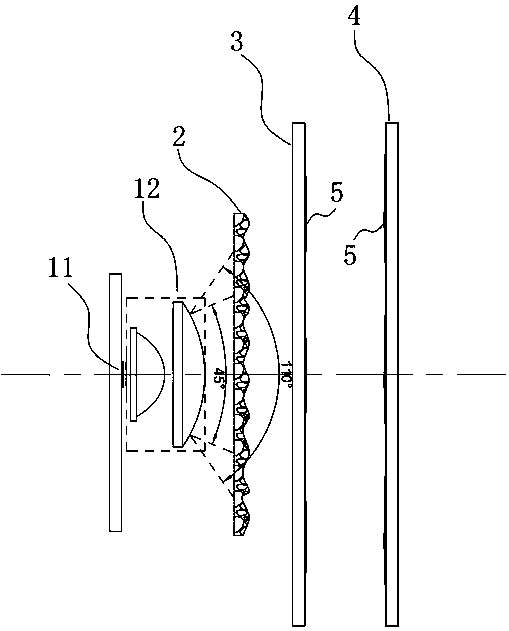
[0071] Embodiment one, as attached Figure 11 As shown, the scattering lens (2) is fixed, the free-form plano-convex lens A (3) and the free-form plano-convex lens B (4) slide back and forth in their respective planes, and the free-form plano-convex lens A (3) and the free Curved plano-convex lens B (4) is relatively moving:

[0072] In this state, the multiple light and dark water patterns formed by the light passing through the free-form plano-convex lens A (3) will follow and move,

[0073] The multiple light and dark water pattern patterns formed by the light passing through the free-form plano-convex lens B (4) will also follow the movement, and the two multiple light and dark water pattern patterns will be dynamically superimposed, and you will see continuous light and shade at this time The effect of compound changes, that is, the 3D undulating spot effect of the water pattern, is essentially the effect of continuous changes in the light intensity difference in differe...

Embodiment 2

[0074] Embodiment two, as attached Figure 12 As shown, the free-form plano-convex lens A (3) is fixed, the diffuser lens (2) and the free-form plano-convex lens B (4) slide back and forth in their respective planes, and the diffuser lens (2) and the free-form plano-convex lens B(4) is relative motion:

[0075] It can be understood that the optical principle of the second embodiment is the same as that of the first embodiment, which means that the free-form surface plano-convex lens A (3) and the free-form surface plano-convex lens (3) are relative to the scattering lens (2). Motion, that is, the relationship between the three motion states described in Embodiment 1, the only difference is that the light passes through the free-form plano-convex lens A (3) to form multiple light and dark water pattern patterns and the light passes through the free-form plano-convex lens B ( 4) The superposition methods of the multiple light and dark water pattern patterns formed are different...

Embodiment 3

[0076] Embodiment three, as attached Figure 13 As shown, the free-form plano-convex lens B (4) is fixed, the diffuser lens (2) and the free-form plano-convex lens A (3) slide back and forth in their respective planes, and the diffuser lens (2) and the free-form plano-convex lens A(3) is relative motion:

[0077] It can be understood that the optical principle of the third embodiment is the same as that of the first embodiment, which means that the free-form surface plano-convex lens A (3) and the free-form surface plano-convex lens (3) are relative to the scattering lens (2). Motion, that is, the relationship between the three motion states described in Embodiment 1, the only difference is that the light passes through the free-form plano-convex lens A (3) to form multiple light and dark water pattern patterns and the light passes through the free-form plano-convex lens B ( 4) The superposition methods of the multiple light and dark water pattern patterns formed are differen...


PUM

PropertyMeasurementUnit
Heightaaaaaaaaaa
Light emitting areaaaaaaaaaaa

Abstract

The invention discloses a double-sheet sliding type lamp optical system capable of generating the water-wave type 3D fluctuation effect. According to the invention, the light of an LED light source isconverged within the range of 45-110 degrees through a condensing lens. The light passes through an irregular prism on a scattering lens to be scattered into heat-dissipation nonlinear light rays different in light intensity difference, wherein the height H of the irregular prism is 0.02mm<=H<=1.4mm. After that, the light rays pass through a free-form-surface planoconvex lens A and a free-form-surface planoconvex lens B, wherein the free-form-surface planoconvex lens A and the free-form-surface planoconvex lens B are composed of a plurality of free-form-surface lenses c which are arranged inan array mode. The projection outline of each free-form-surface lens c is in the water wave shape, and the curvature radius R of the free-form-surface lens c ranges from -25mm to 25mm. Therefore, thepositive and negative lens effect is formed. When an image is formed on the same imaging surface, an image with more obvious light intensity difference contrast can be formed. In addition, any two ofthe scattering lens, the free-form-surface lens A and the free-form-surface lens B relatively slide in the above plane. Finally, a 3D fluctuant light spot effect of a water wave pattern is formed.

Description

technical field [0001] The invention belongs to the field of stage and landscape lamp lighting, in particular to the field of water pattern light optical systems. Background technique [0002] The stage lighting market in modern society is more and more widely used, and there are more and more places of application. Sometimes it is necessary to let the lamps hit the buildings to produce lighting effects, which can beautify the scenery and enhance the atmosphere. The current market There are few water pattern lamps with water pattern effects in the world. This kind of water pattern lights with water pattern effects will emit the effect of flowing water, which is very beautiful and beautiful. At present, the water pattern effect of the water pattern lamp on the market has the following several ways of expression. [0003] The first is achieved by the rotation of the water pattern drum. For example, the utility model patent with the publication number CN206093600U, a new type...

Claims


Application Information

Patent Timeline
IPC IPC(8): F21S10/00F21V5/00F21V5/04F21V5/08F21Y115/10
CPCF21S10/00F21V5/007F21V5/008F21V5/04F21V5/048F21V5/08F21Y2115/10
Inventor 许法卿薛金山
Owner GUANGZHOU DASEN LIGHTING ELECTRONICS
Why Eureka
Try Eureka