Hydraulic casting unit

A technology for hydraulic and die-casting machines, applied in the field of hydraulic casting units, which solves the problem of not always being able to ensure the reproducibility of the opening and closing moments of the central valve

Active Publication Date: 2019-07-05
ROBERT BOSCH GMBH
View PDF9 Cites 0 Cited by
  • Summary
  • Abstract
  • Description
  • Claims
  • Application Information

AI Technical Summary

Problems solved by technology

It has been found that with the known hydrocasting units it is not always possible to ensure a complete reproducibility of the opening and closing times of the 2 / 2-way center valve

Method used


Image

  • Hydraulic casting unit
  • Hydraulic casting unit
  • Hydraulic casting unit

Examples


Embodiment Construction

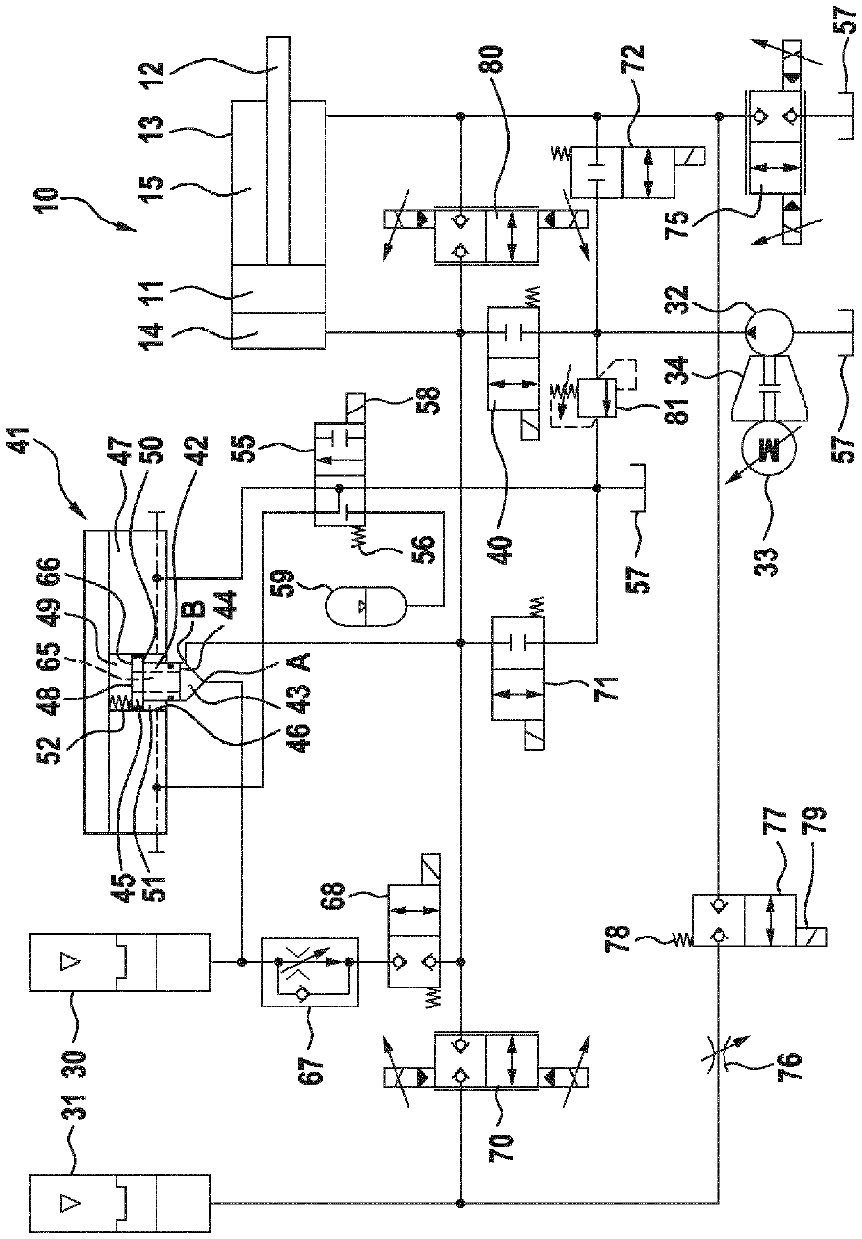
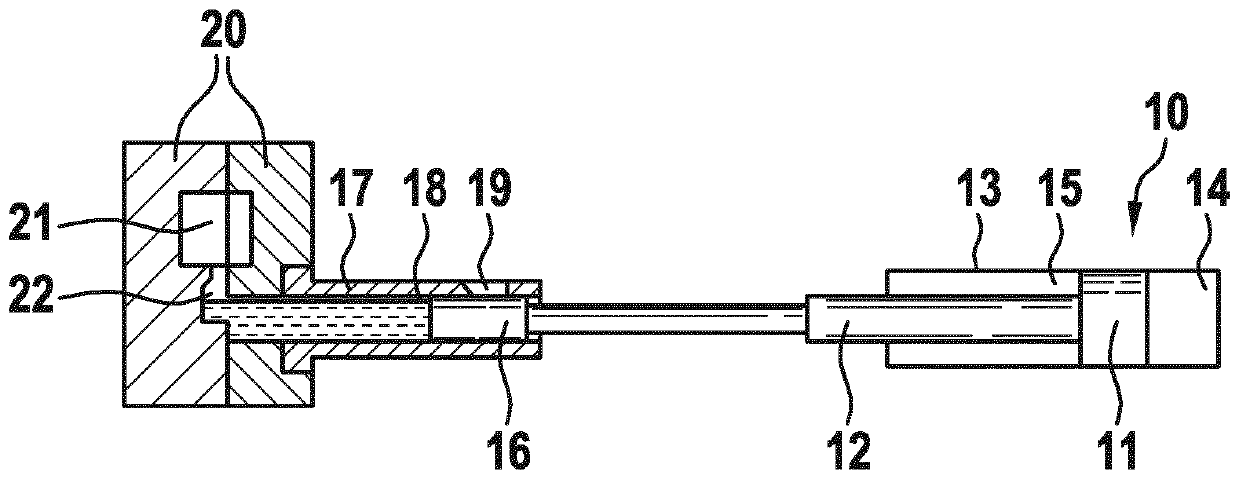
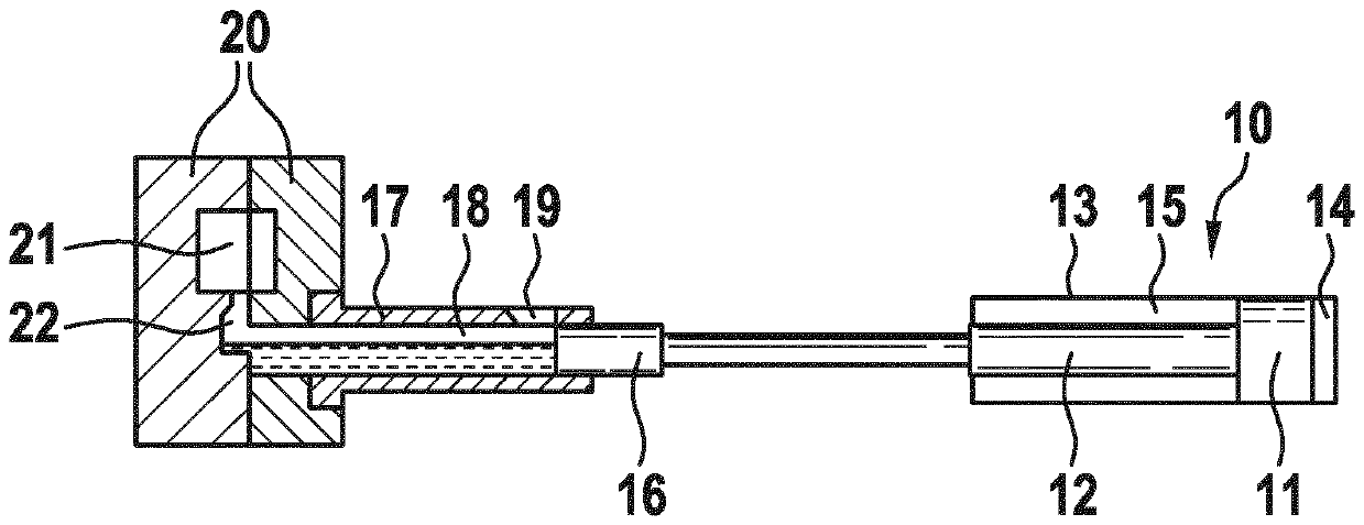
[0023] according to Figure 1 to Figure 4 , the die-casting machine comprises a casting cylinder 10 which is configured as a differential cylinder and has a piston 11 and a piston rod 12 which extends from the side of the piston 11 through the interior of the casting cylinder and at the cover from the The casing 13 protrudes outward. In the interior of the casting cylinder 10 , a completely cylindrical bottom-side pressure chamber 14 and an annular rod-side pressure chamber 15 are separated from each other by a piston 11 .

[0024] Fastened on the piston rod 12 is a cast piston 16 which is linearly movable in an injection chamber 18 which is formed in the injection sleeve 17 . In the injection sleeve 17 is located a filling opening 19 for a liquid or pasty molding compound, from which the workpiece to be formed is to be formed. The injection sleeve 17 is assembled with a mold 20 by means of which a mold cavity 21 is formed, which can be filled with molding material for the p...


PUM


Abstract

The invention relates to a hydraulic casting unit which is provided for a moulding machine, in particular for a high pressure die casting machine, and which has a casting cylinder with a pressure chamber which acts in the extending direction, a low pressure source, to which the pressure chamber of the casting cylinder is connected fluidically during a preliminary filling phase and / or a mould filling phase, and a high pressure source, to which the pressure chamber of the casting cylinder is connected fluidically during a holding pressure phase. The fluidic connection between the pressure chamber of the casting cylinder and the low pressure source can be opened and closed in a controlled manner by way of a pilot-controlled 2 / 2-way seat valve which has a first connector which is connected tothe low pressure source and a second connector which is connected to that pressure chamber of the casting cylinder which acts in the extending direction. The 2 / 2-way seat valve has a movable main piston with a first control surface, on which the main piston is loaded in the closing direction by the pressure which prevails at a connector, and with a second control surface. Moreover, the 2 / 2-way seat valve has a pilot control valve. The main piston can be loaded in the opening direction on a second control surface by a control pressure which can be switched on by way of the pilot control valve.A hydraulic casting unit is to be designed in such a way that the 2 / 2-way seat valve is flowed through with a very low pressure loss and closes with a low switching time at a time with high repeatingaccuracy in the case of switching of the pilot control valve. This is achieved by virtue of the fact that the main piston is loaded on the first control surface by the low pressure which prevails at the first connector, and that the force which is generated on the second control surface by the control pressure which can be switched on is greater than the force which is generated on the first control surface by the low pressure.

Description

technical field [0001] The invention relates to a hydraulic casting unit which is provided for a forming machine, in particular a die casting machine, and which has a casting cylinder, a low pressure source and a high pressure source, the casting cylinder having a A pressure chamber acting in the direction of extension, the pressure chamber of the casting cylinder being fluidly connected to the low pressure source during the prefilling phase and / or the mold filling phase, the pressure chamber of the casting cylinder being connected to the Fluid connection to the high pressure source described above. The fluid connection between the pressure chamber of the casting cylinder and the low pressure source is opened and closed by a pre-controlled 2 / 2-way central valve having a first port and a second ports, the first port is connected to the low pressure source, and the second port is connected to a pressure chamber of the casting cylinder acting in the extension direction. The 2 / 2...

Claims


Application Information

Patent Timeline
Patent Type & Authority Applications(China)
IPC IPC(8): B22D17/20B29C45/82B22D17/32
CPCB22D17/2015B22D17/32
Inventor D-W.赫罗德H.安格特
Owner ROBERT BOSCH GMBH
Why Eureka
Try Eureka