Diaphragm valve and method for manufacturing diaphragm valve

一种膜片阀、阀壳体的技术,应用在隔膜阀、阀的操作/释放装置、隔膜等方向,能够解决支承单元不能够运动地固定阀壳体等问题

Pending Publication Date: 2021-02-23
FESTO AG & CO KG
View PDF15 Cites 0 Cited by
  • Summary
  • Abstract
  • Description
  • Claims
  • Application Information

AI Technical Summary

Problems solved by technology

[0006] In order to solve the stated object, it is provided in a diaphragm valve of the type mentioned at the outset that the bearing unit occupying the working position is fastened immovably on the valve housing by fastening means, wherein the bearing unit and the valve housing are as follows The design is coordinated with one another, so that the bearing unit can be continuously displaced in the height direction within the valve housing without fastening measures in order to adjust the height distance occupied by the bearing webs with respect to the bottom wall.

Method used


Image

  • Diaphragm valve and method for manufacturing diaphragm valve
  • Diaphragm valve and method for manufacturing diaphragm valve
  • Diaphragm valve and method for manufacturing diaphragm valve

Examples


Embodiment Construction

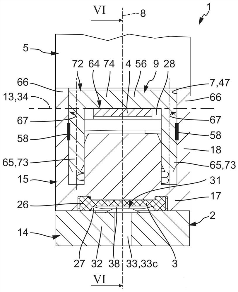
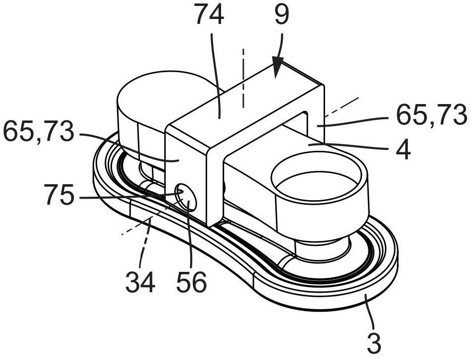
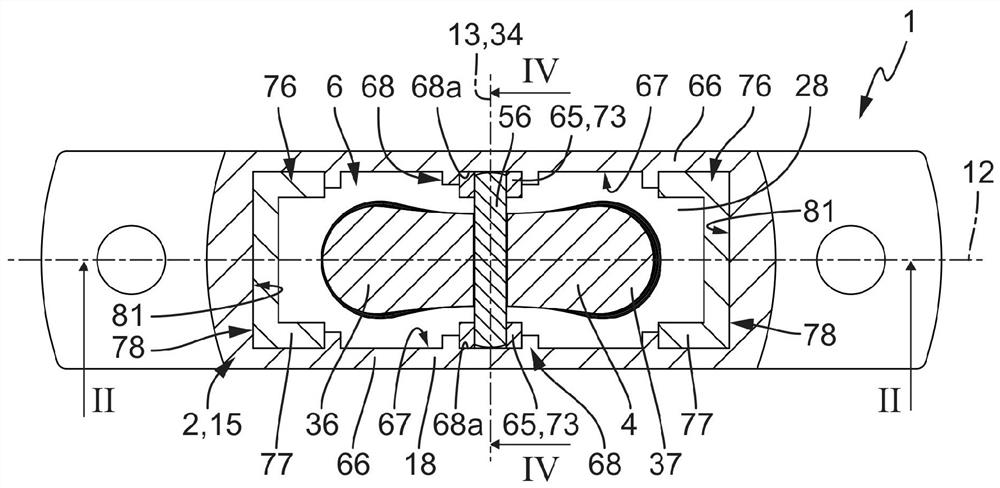
[0041] The diaphragm valve identified in its entirety with the reference number 1 has a valve housing 2 , a control diaphragm 3 acting as a valve element, a switching rocker 4 for actuating the control diaphragm 3 and a switching rocker for actuating 4 of the drive mechanism 5 as a basic component.

[0042] Furthermore, the diaphragm valve 1 has a bearing unit 9 , by means of which the switching rocker 4 is supported so as to be pivotable with respect to the valve housing 2 .

[0043] The valve housing 2 delimits a housing interior 6 in which the control membrane 3 , the bearing unit 9 and the switching rocker 4 are accommodated. The housing interior 6 has an interior opening 7 which is closed by a drive mechanism 5 which is arranged on the valve housing 2 .

[0044] The valve housing 2 has an imaginary vertical axis 8 which simultaneously delimits the vertical axis of the entire diaphragm valve 1 . The axial direction of the vertical axis 8 is referred to as the height dire...


PUM


Abstract

The invention relates to a diaphragm valve (1) having a valve housing (2), in which a switching lever (4) is arranged which can be pivoted about a pivot axis (34) and which interacts with a control diaphragm (3) in order to open and close at least one valve channel (33). The pivot axis (34) is delimited by a support web (56), on which the switching rocker (4) rests in a pivotable manner. The support web (56) is an integral component of a support unit (9) which is fastened to the valve housing (2) in a drive chamber (28) by means of fastening means (58). The bearing unit (9) can be displaced without the fastening means (58) in order to adjust a desired height distance of the bearing web (56). The invention further relates to a method for producing such a diaphragm valve (1).

Description

technical field [0001] The invention relates to a diaphragm valve having a valve housing which delimits a housing interior space which is subdivided in a fluid-tight manner by a flexible control diaphragm into a control chamber and a drive chamber, wherein the control chamber is delimited by a bottom wall of the valve housing that is vertically opposite the control membrane, said bottom wall being penetrated by a plurality of valve channels leading into the control chamber, and wherein the A switching rocker that interacts drivingly with the control membrane is arranged in the drive chamber, which can be swiveled back and forth about a pivot axis relative to the valve housing by means of a drive mechanism during a switching movement in order to control the valve. The diaphragm is deformed in such a way that the control diaphragm selectively opens or closes at least one of the valve channels, wherein the pivot axis of the switching rocker passes through the entire body of the b...

Claims


Application Information

Patent Timeline
Patent Type & Authority Applications(China)
IPC IPC(8): F16K11/04F16K31/06F16K27/02
CPCF16K11/04F16K31/0655F16K31/0675F16K27/0236F16K31/0682F16K31/0641F16K27/0263F16K7/16
Inventor A·比勒
Owner FESTO AG & CO KG
Why Eureka
Try Eureka