Self-recovery device of detecting pipeline passage by diaphragm type blood withdrawal method

A test tube and diaphragm-type technology, which is applied in the field of diaphragm-type self-recovery device for blood withdrawal test pipeline path, can solve the problems of difference in withdrawal force and distance, low efficiency, and many steps, so as to achieve low production cost and improve efficiency And the effect of quality and easy operation

Pending Publication Date: 2019-07-09
杨恚
View PDF6 Cites 2 Cited by
  • Summary
  • Abstract
  • Description
  • Claims
  • Application Information

AI Technical Summary

Problems solved by technology

This method relies on the medical staff to manually pull the syringe push rod, which requires the medical staff to operate with both hands. There are many steps and low efficiency. The withdrawal force and distance will vary due to different operating habits.

Method used


Image

  • Self-recovery device of detecting pipeline passage by diaphragm type blood withdrawal method
  • Self-recovery device of detecting pipeline passage by diaphragm type blood withdrawal method
  • Self-recovery device of detecting pipeline passage by diaphragm type blood withdrawal method

Examples


Embodiment 1

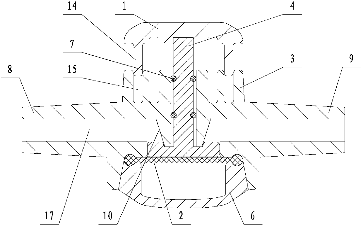
[0031] Such as Figure 1A , Figure 1B As shown, the driving connector of this embodiment includes a negative pressure button 1 and a negative pressure push rod 4. The axial section of the negative pressure push rod 4 is an inverted "T" shape, and the transverse side of the "T" shape is located on the piston cylinder 3. Inside, it abuts against the upper surface of the elastic membrane 2 . The other end of the negative pressure push rod 4 (ie the vertical side of the "T" shape) is located outside the piston cylinder 3 and connected to the negative pressure button 1 . The negative pressure button 1 of the present embodiment has a top plate, and a plurality of guide columns 14 are arranged on the lower surface of the top plate; the upper part of the piston cylinder 3 is provided with the same number of guide grooves 15 as the guide columns 14, and each guide column 14 is inserted Set in a guide groove 15. There is a space for the negative pressure button 1 to be pressed down b...

Embodiment 2

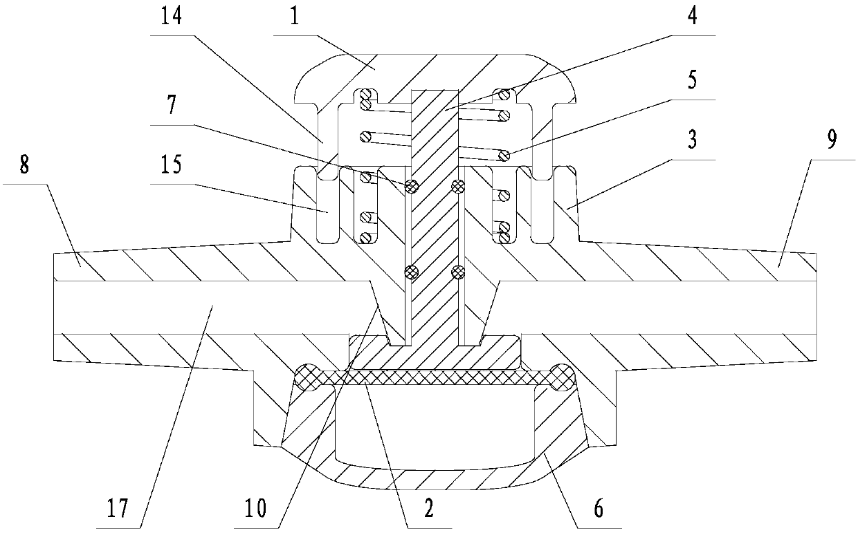
[0035] Such as Figure 2A , Figure 2B As shown, the difference between the present embodiment and the first embodiment is that: the present embodiment accommodates a reset device between the top plate of the negative pressure button 1 and the outer surface of the piston cylinder 3, the reset device is a spring 5, and one end of the elastic 5 is connected to the The outer surface of the piston cylinder 3 abuts, and the other end abuts against the lower surface of the top plate of the negative pressure button 1 . All the other are identical with embodiment one.

[0036]During detection, no liquid flow occurs at the inlet 9. Press the negative pressure button 1 with your finger, you need to overcome the elastic force of the spring 5, press the negative pressure push rod 4 down, and press the elastic membrane 2 through the negative pressure push rod 4, so that the elastic membrane 2 is elastically deformed downward, and then the upper part of the elastic membrane 2 The volume ...

Embodiment 3

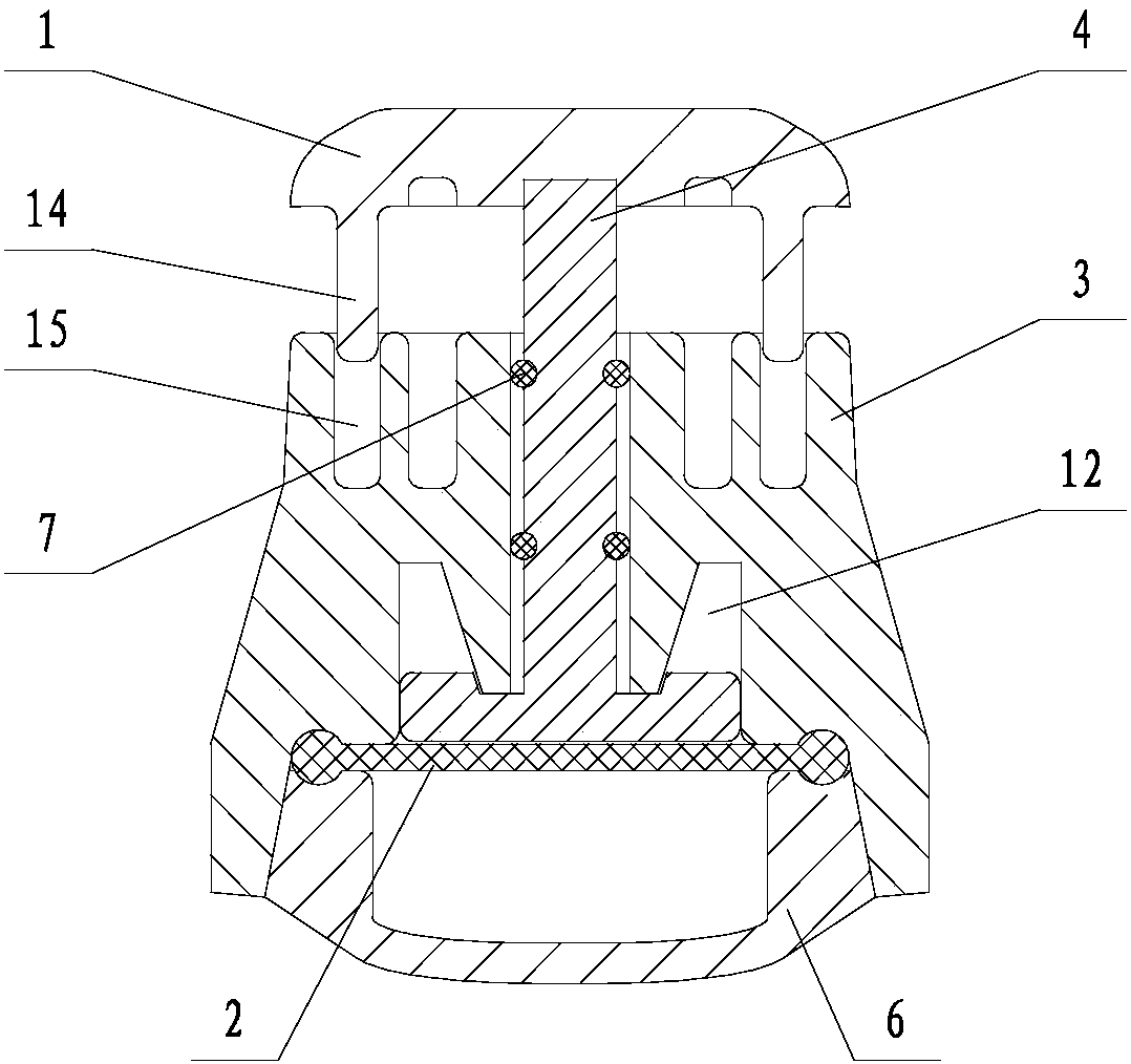
[0038] Such as Figure 3A , Figure 3B As shown, the difference between the present embodiment and the second embodiment is that the present embodiment is provided with a recovery push rod 11 in the space between the negative pressure push rod 4 and the bottom of the piston cylinder 3 (i.e. the lower cover 6). One end of the rod 11 abuts against the elastic membrane 2 , and the other end is inserted into the through hole 13 opened at the bottom of the piston cylinder 3 . The spring 5 is sheathed on the recovery push rod 11 , and the two ends abut against the bottom of the recovery push rod 11 and the piston cylinder 3 respectively. All the other are identical with embodiment two.

[0039] During detection, no liquid flow occurs at the inlet 9. Press the negative pressure button 1 with your finger, press the elastic membrane 2 through the negative pressure push rod 4, make the elastic membrane 2 elastically deform downward, and then increase the volume of the airtight cavity...


PUM


Abstract

The invention relates to a passage detection device of an indwelling catheter, in particular to a self-recovery device of detecting a pipeline passage by a diaphragm type blood withdrawal method. Thedevice is characterized in that an elastic film is hermetically connected to a piston cylinder, and a cavity body in the piston cylinder is divided into two parts of space by the elastic film, whereinone part of the space is communicated between the indwelling catheter and a liquid source pipeline in a vein blood vessel, and the other part of the space provides a deformation space for the elasticfilm; the elastic film is connected with a driving connecting piece, the elastic film elastically deforms in the piston cylinder by pressing the driving connecting piece, negative pressure is formedbetween the indwelling catheter and the liquid source pipeline in the vein blood vessel, and whether blood flows back at the indwelling catheter or not is detected through the formed negative pressure; and the detected elastic film returns to an initial state after releasing the driving connecting piece. The device can be connected with the indwelling catheter for a long time, is used for checkingwhether the pipeline is unobstructed or not before infusion, reduces the individual difference problem of manual operation while simplifying the operation of withdrawing blood, and obviously improvesthe efficiency and quality of nursing operation of the indwelling catheter before infusion.

Description

technical field [0001] The invention relates to a passage detection device for an indwelling catheter, in particular to a diaphragm-type self-recovering device for testing pipeline passages by withdrawing blood. Background technique [0002] In 2014, the Ministry of Health of my country promulgated the latest "Nursing Practices for Intravenous Infusion Therapy", which clearly stipulates that central venous catheters (CVC), including peripherally inserted central venous catheters (PICC), must be drawn back to confirm that the catheter is in the vein. . In the "2016 Practice Standards for Infusion Therapy" flushing and locking standards of INS: Before each infusion, the vascular access device should be flushed and blood should be withdrawn to evaluate the function of the catheter and prevent complications. In clinical infusion work, the common inspection method is to first connect the syringe nozzle with the infusion tube, pull the syringe push rod, and observe whether there i...

Claims


Application Information

Patent Timeline
Patent Type & Authority Applications(China)
IPC IPC(8): A61M5/14
CPCA61M5/14A61M2205/70A61M2005/1401
Inventor 杨恚丛利刘伟
Owner 杨恚
Why Eureka
Try Eureka