Bending mold

A technology for bending molds and mold bases, which is applied in the field of mechanical processing, and can solve problems such as increased mold processing costs, extended mold development cycles, and rebounds at bends

Inactive Publication Date: 2019-07-09
GUANGDONG EVERWIN PRECISION TECH
View PDF9 Cites 1 Cited by
  • Summary
  • Abstract
  • Description
  • Claims
  • Application Information

AI Technical Summary

Problems solved by technology

The current problem in bending processing is that most metal products will rebound at the bend after bending
The problem with this approach is that the bending angle calculated by using the rebound rate is a theoretical value, and there will be errors between the theoretically calculated bending angle and the actual processing. Therefore, for the traditional ben...

Method used


Image

  • Bending mold
  • Bending mold
  • Bending mold

Examples


Embodiment Construction

[0032] In order to facilitate the understanding of the present invention, the present invention will be described more fully below with reference to the associated drawings. Preferred embodiments of the invention are shown in the accompanying drawings. However, the present invention can be embodied in many different forms and is not limited to the embodiments described herein. On the contrary, these embodiments are provided to make the understanding of the disclosure of the present invention more thorough and comprehensive.

[0033] It should be noted that when an element is referred to as being “fixed” to another element, it can be directly on the other element or there can also be an intervening element. When an element is referred to as being "connected to" another element, it can be directly connected to the other element or intervening elements may also be present.

[0034] Unless otherwise defined, all technical and scientific terms used herein have the same meaning as...


PUM


Abstract

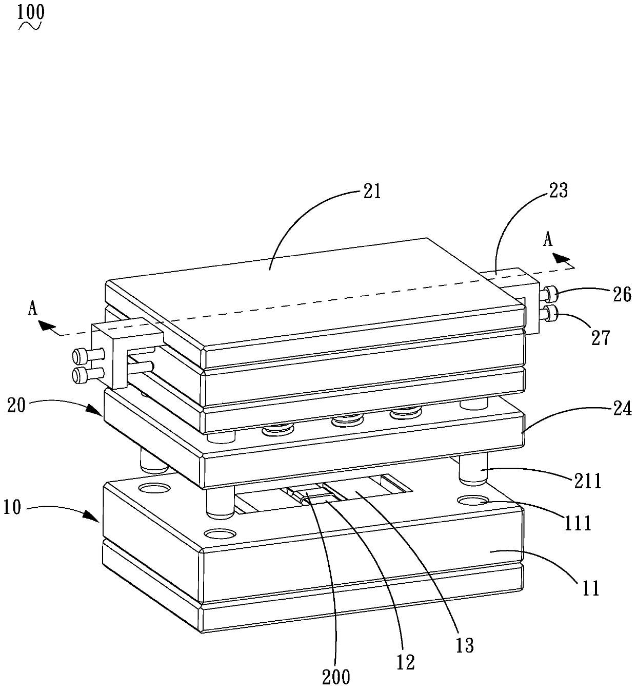
The invention relates to a bending mold. The bending mold comprises a lower mold assembly and an upper mold assembly parallel to the lower mold assembly. The lower mold assembly includes a lower moldbase, a forming block connected to the lower mold base and a bending push block slidably connected to the lower mold base. The upper mold assembly includes an upper mold base, a slotting tool slidablyconnected to the upper mold base and an adjusting block slidably connected to the upper mold base. One end of the slotting tool extends out of the upper mold seat and extends toward the lower mold seat to drive the bending push block to slide toward the forming block. The adjusting block is slidably disposed on the upper mold base and one end of the adjusting block extends to the outer side of the upper mold base. The adjusting block is slidably connected with the slotting tool to adjust the amount of extension of the slotting tool relative to the upper mold base. According to the bending mold, in the mold-testing process, by adjusting the adjusting block without modifying the angle of a forming part in the mold, the purpose of adjusting the bending angle of a product can be achieved, themold machining cost can be reduced, and the development cycle of the mold can be shortened.

Description

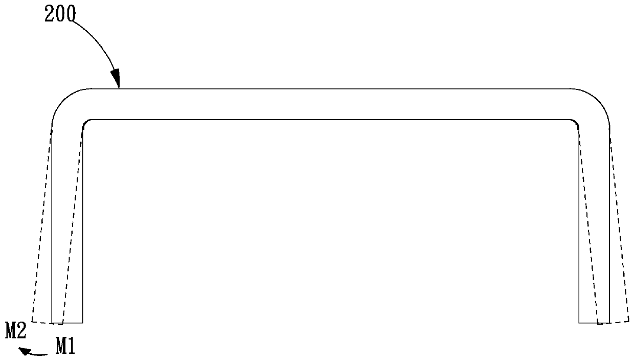
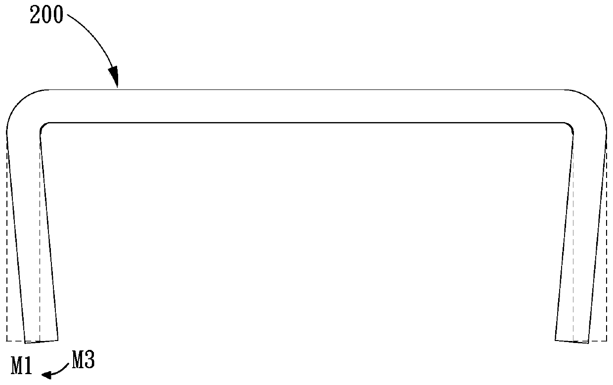
technical field [0001] The invention relates to the technical field of mechanical processing, in particular to a bending die. Background technique [0002] In the product manufacturing process, the bending process of the product is sometimes involved, that is, the bending deformation of the product is forced to produce a preset angle by applying force to the product. The problem with the current bending process is that most metal products will rebound at the bend after bending. For example, if figure 1 As shown, in order to bend the product 200 into a right angle, the traditional method is to bend the product 200 into a right angle in a bending mold. However, when the product 200 is out of the mold, the bend will rebound, that is, the end of the bend will rebound from the M1 position to the M2 position when the mold is out, so that the product 200 after the mold out cannot meet the right angle requirement. [0003] For the problem of rebound, the corrective method adopted...

Claims


Application Information

Patent Timeline
IPC IPC(8): B21D37/10
CPCB21D37/10
Inventor 蔡晓彬
Owner GUANGDONG EVERWIN PRECISION TECH
Why Eureka
Try Eureka