Multi-station combined fixture

A combined fixture and multi-station technology, which is applied in the direction of manufacturing tools, clamping, positioning devices, etc., can solve the problem of cumulative error of multiple processing surfaces

Inactive Publication Date: 2019-07-09
陈金梅
View PDF0 Cites 0 Cited by
  • Summary
  • Abstract
  • Description
  • Claims
  • Application Information

AI Technical Summary

Problems solved by technology

[0003] The purpose of the present invention is to improve a multi-station combined fixture, thereby using the multi-station combined

Method used


Image

  • Multi-station combined fixture
  • Multi-station combined fixture

Examples


Embodiment Construction

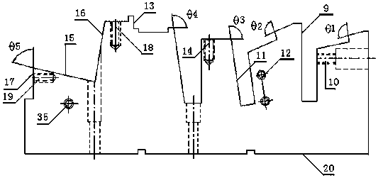
[0013] The present invention will be further described below in conjunction with accompanying drawings and embodiments.

[0014] Examples, see attached figure 1 : The present invention relates to a multi-station combined fixture, comprising a first positioning surface 9, a first screw hole 10, a first matching angle θ1, a second positioning surface 11, a second screw hole 12, a second matching angle θ2, a first Three positioning surfaces 13, third screw holes 14, third matching angle θ3, fourth matching angle θ4, fourth positioning surfaces 15, fifth positioning surfaces 16, sixth positioning surfaces 17, fourth screw holes 18, fifth screw holes Hole 19 , sixth screw hole 35 , fifth matching angle θ5 , and bottom surface 20 . The multi-station means that there is more than one station in the combined fixture, and each station is signed by the surface to be processed, from right to left, including the outer plane station, theta bevel station, the outer vertical surface station...


PUM


Abstract

The invention relates to a multi-station combined fixture. An outer plane station, a theta oblique plane station, an outer vertical plane station and a beta oblique plane station are formed from rightto left through structural design, and thus the multi-station combined fixture can be used for reducing the number of times of adjusting a machine tool, solving the problem of cumulative errors of multiple machining surfaces and improving machining accuracy.

Description

technical field [0001] The invention relates to a multi-station combined fixture. Background technique [0002] With the rapid development of the machinery manufacturing industry, the replacement of products is getting faster and faster. The traditional mass production mode is gradually replaced by the medium and small batch production mode. The mechanical manufacturing system needs to have high flexibility to adapt to this change. Foreign countries have regarded the flexible manufacturing system as an effective means of developing new products, and regard it as the main development direction of the machinery manufacturing industry. The focus of flexibility is mainly on machine tools and tooling, and combined fixtures are the focus of tooling flexibility. The combination fixture is a kind of standardized, serialized, and highly versatile process equipment. It is composed of a set of pre-manufactured standard components and assemblies of various shapes, specifications, and s...

Claims


Application Information

Patent Timeline
IPC IPC(8): B23Q3/06
CPCB23Q3/06
Inventor 陈金梅
Owner 陈金梅
Why Eureka
Try Eureka