Lamp rubber part forming mold

A technology for forming molds and rubber parts, applied in the field of forming molds for rubber parts of lamps, can solve problems such as uneven shape of finished parts, damage to finished parts, and increase in enterprise costs, and achieve the effect of clear thinking, easy assembly, and improved work efficiency.

Inactive Publication Date: 2019-07-09
SYNERGY HANIL PRECISION POLYMER TECH CO LTD
View PDF0 Cites 0 Cited by
  • Summary
  • Abstract
  • Description
  • Claims
  • Application Information

AI Technical Summary

Problems solved by technology

[0002] For the molding of the lamp table and lamp tube interface connector, it is basically completed by injection molding process. The previous molding process is very simple. After the mold is closed, the mold is injected with glue, and the mold is opened after cooling to complete the molding of the product. , which also reflects the simplicity of the product structure. For the molding of the interface connectors of lampstands and lamp tubes with more complex structures, although the same glue injection process is used to complete the product molding, more detailed design is required to ensure product quality. , to improve work efficiency, the lamp table lamp tube interface connector is a slender structure, and the general injection molding process is difficult to fully fill, and it is easy to cause the shape of the finished part to be not particularly uniform, and some areas are thick and some The area is thin, which increases the cost of the enterprise virtually, and improper demoulding treatment will also cause damage to the finished product. It is necessary to improve the mold structure to improve the quality of the product.

Method used


Image

  • Lamp rubber part forming mold
  • Lamp rubber part forming mold
  • Lamp rubber part forming mold

Examples


Embodiment Construction

[0025] The specific implementation manners of the present invention will be briefly described below in conjunction with the accompanying drawings.

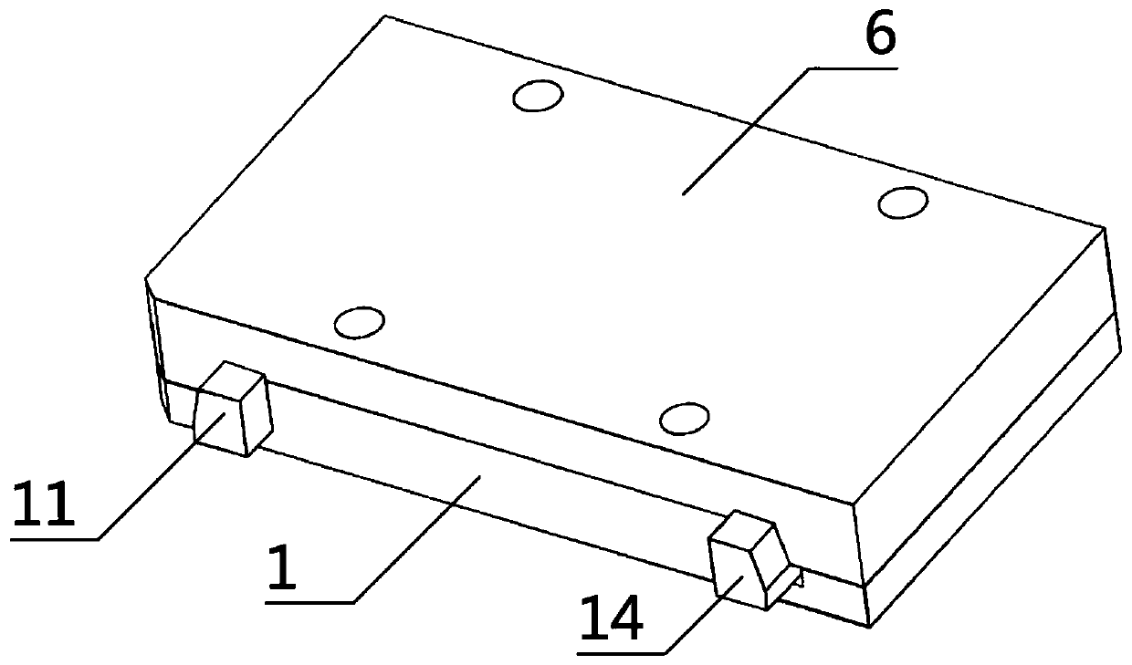
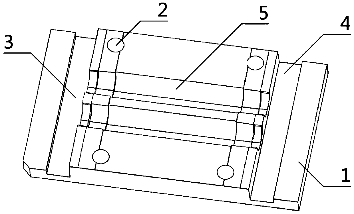
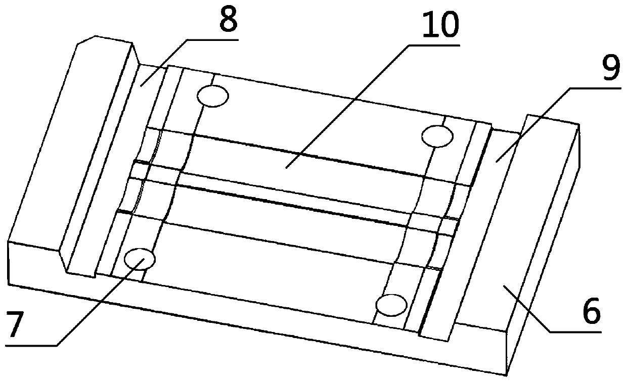
[0026] Such as figure 1 , figure 2 , image 3 , Figure 4 , Figure 5 , Image 6 , Figure 7 , Figure 8 A molding die for rubber parts of lamps is shown, which is characterized in that it consists of a lower template 1, an upper template 6, a first inlay 11 and a second inlay 14, the upper template 6 is located on the upper part of the lower template 1, and the The upper formwork 6 is movably connected to the lower formwork 1, and the first inlay 11 and the second inlay 14 are located inside the lower formwork 1 and the upper formwork 6 after mold closing. The first inlay 11 and the second inlay 14 are respectively movably connected with the lower formwork 1 and the upper formwork 6, the second inlay 14 is located on one side of the first inlay 11, the second inlay 14 is in movably connected with the first inlay 11, the ...


PUM


Abstract

The invention aims to provide a lamp rubber part forming mold. According to the technical scheme of the lamp rubber part forming mold, the lamp rubber part forming mold is composed of a lower mold plate, an upper mold plate, a first insert strip and a second insert strip; the lower mold plate is provided with four lower mold plate positioning holes, a first insert strip clamping station lower groove, a second insert strip clamping station lower groove and two insert strip lower forming grooves; and the upper mold plate is provided with four upper mold plate positioning holes, a first insert strip clamping station upper groove, a second insert strip clamping station upper groove and two insert strip upper forming grooves. The mold is used for forming a connecting piece at the position of anexternal connector of a lamp pipe of a lamp platform, assembling, disassembling, mold closing and demolding are facilitated, and a glue overflowing phenomenon is prevented; the mold is distinct in structural concept and easy to operate; and by means of the structural design of inserting or pulling for mold closing, assembling of the mold and demolding separation of a finished product are more facilitated, the working efficiency is improved, the sealing performance is higher, the glue overflowing phenomenon in the injection molding process cannot be caused, the lamp rubber part forming mold ismore environmental-friendly and practical, and the machining quality of the product is improved.

Description

technical field [0001] The invention relates to the field of mold fixtures, in particular to a mold for forming rubber parts of lamps. Background technique [0002] For the molding of the lamp table and lamp tube interface connector, it is basically completed by injection molding process. The previous molding process is very simple. After the mold is closed, the mold is injected with glue, and the mold is opened after cooling to complete the molding of the product. , which also reflects the simplicity of the product structure. For the molding of the interface connectors of lampstands and lamp tubes with more complex structures, although the same glue injection process is used to complete the product molding, more detailed design is required to ensure product quality. , to improve work efficiency, the lamp table lamp tube interface connector is a slender structure, and the general injection molding process is difficult to fully fill, and it is easy to cause the shape of the f...

Claims


Application Information

Patent Timeline
Patent Type & Authority Applications(China)
IPC IPC(8): B29C45/26B29C45/40
CPCB29C45/26B29C45/2608B29C45/40
Inventor 魏俊峰鲁晓波
Owner SYNERGY HANIL PRECISION POLYMER TECH CO LTD
Why Eureka
Try Eureka