Ultra-thin mobile phone support

A mobile phone holder, ultra-thin technology, applied in the direction of transportation and packaging, vehicle parts, etc., can solve the problems of large volume, thick mobile phone holder, occupying space in the car, etc. The effect of inner space

Pending Publication Date: 2019-07-09
SHENZHEN CHEANDA ELECTROMECHANICAL
View PDF0 Cites 3 Cited by
  • Summary
  • Abstract
  • Description
  • Claims
  • Application Information

AI Technical Summary

Problems solved by technology

[0002] There are more and more cars on the market and mobile phone navigation software is getting better and better services. In order to drive safely when navigating, car owners use more and more car phone holders. However, the current structure of mobile phone holders is limited, and the thickness of mobile phone holders is relatively thick and bulky. , At present, the new technology uses the lever to form an "X" shape to form

Method used


Image

  • Ultra-thin mobile phone support
  • Ultra-thin mobile phone support
  • Ultra-thin mobile phone support

Examples


Example Embodiment

[0034] Example 1

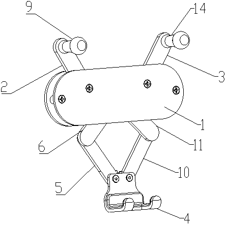
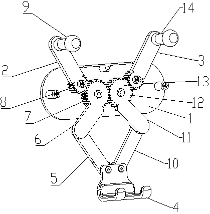
[0035] Such as Figure 1 to Figure 4 As shown, an ultra-thin mobile phone holder includes a housing 1, a left clamping rod 2, a right clamping rod 3, a pawl 4, and a transmission mechanism. The pawl 4 is arranged under the housing 1. The pawl 4 is connected to the left clamping rod 2 and the right clamping rod 3 through a transmission mechanism. The transmission mechanism includes a left connecting rod 5, a left shifting rod 6, a right connecting rod 10, and a right shifting rod 11. One end of the connecting rod 5 is rotatably connected with the pawl 4, the other end of the left connecting rod 5 is rotatably connected with one end of the left shift lever 6, and the other end of the left shift lever 6 is provided with a left driving gear 7 , One end of the left clamping lever 2 is provided with a left driven gear 8 meshing with the left driving gear 7, and the other end of the left clamping lever 2 is a left clamping portion 9 for clamping a mobile phone. The ...

Example Embodiment

[0041] Example 2

[0042] Such as Figure 7 As shown, embodiment 2 is the same as embodiment 1, but the difference is that there is a rotating shaft at the connection of the claw 4 and the left link 5 and the right link 10 in the embodiment 1, while the claw 4 and the left link of the embodiment 2 There is only one rotating shaft at the connection between 5 and the right connecting rod 10, that is, the two rotating shafts at this place in Embodiment 1 coincide.

Example Embodiment

[0043] Example 3

[0044] Such as Picture 8 As shown, embodiment 3 is the same as embodiment 2, except that the left driving gear 7 and right driving gear 12 in embodiment 2 mesh with each other, while the left driven gear 8 and right driven gear in embodiment 3 The gears 13 mesh with each other.


PUM


Abstract

The invention relates to an ultra-thin mobile phone support. The support comprises a shell body, a left clamping rod, a right clamping rod, a supporting claw and a transmission mechanism, the supporting claw is arranged under the supporting claw and connected with the left clamping rod and the right clamping rod through the transmission mechanism, and the transmission mechanism comprises a left connection rod, a left stirring rod, a right connection rod and a right stirring rod; one end of the left/right connection rod is connected with the supporting claw, the other end of the left/right connection rod is rotatably connected with one end of the left/right stirring rod, a left/right drive gear is arranged at the other end of the left/right stirring rod, and one end of the left/right clamping rod is provided with a left/right driven gear or a left/right driven rack which is meshed with the left/right drive gear. Through tooth meshing of the left clamping rod, the right clamping rod, theleft stirring rod and the right stirring rod, transmission is achieved, in addition, the left clamping rod, the right clamping rod, the left stirring rod and the right stirring rod are in the same plane and are the same in thickness, crossing is not needed, therefore the thickness can be smaller, the occupied space in a car is reduced, and the cleanliness and attractiveness of car interiors are improved.

Description

technical field [0001] The invention relates to an ultra-thin mobile phone bracket. Background technique [0002] There are more and more cars on the market and mobile phone navigation software is getting better and better services. In order to drive safely when navigating, car owners use more and more car phone holders. However, the current structure of mobile phone holders is limited, and the thickness of mobile phone holders is relatively thick and bulky. , At present, the new technology uses the lever to form an "X" shape to form a quadrilateral movable folding gravity mobile phone holder technology. Thicker, thicker mobile phone holders occupy the space in the car and affect the appearance of the interior of the car. Part of the mobile phone holder uses the upper teeth of the clamping rod to engage the mobile phone. It uses springs or torsion springs to clamp the mobile phone. It does not use connecting rods and hooks. Transmission, inconvenient to use. Contents of t...

Claims


Application Information

Patent Timeline
IPC IPC(8): B60R11/02
CPCB60R11/0241B60R2011/0003B60R2011/008
Inventor 张勇华阳勇
Owner SHENZHEN CHEANDA ELECTROMECHANICAL
Why Eureka
Try Eureka