Centric clamping vice

a technology of clamping vices and clamping slots, which is applied in the direction of tools, manufacturing tools, etc., can solve the problems of only a small part of the base support, and the clamping range provided thereby, and achieve the effect of large clamping rang

Inactive Publication Date: 2016-03-29
ROHM GMBH
View PDF18 Cites 4 Cited by
  • Summary
  • Abstract
  • Description
  • Claims
  • Application Information

AI Technical Summary

Benefits of technology

[0006]It is therefore an object of the present invention to reduce the aforementioned disadvantages and to provide a compact centric clamping vice which has a large clamping range.
[0007]This object is achieved in an embodiment, whereby a centric clamping vice having a pair of first slides is assigned to the first carriage, and a pair of second slides is assigned to the second carriage, and the difference between the track width of the first slides and the track width of the second slides is greater than the width of the second slides. In particular, if the first slides and the second slides are oriented facing each other, it is possible to adjust the jaw mounts with respect to each other with the aid of the different track widths, each of which is defined by the distance between the inside surfaces of the slides and the suitable with of the slides, in such a way that the trajectories of the first slides and the second slides do not overlap during the adjustment of the jaw mounts and may thus be guided past each other. It may hereby be easily and effectively ensured that the base support may be given a highly compact design, and workpieces of different sizes may be clamped with the aid of the centric clamping vice according to the present invention.

Problems solved by technology

In the centric clamping vices according to the prior art, however, it has proven to be disadvantageous that the clamping range provided thereby makes up only a small part of the base support.
Thus, centric clamping vices known according to the prior art result in the need to either maintain multiple centric clamping vices having different clamping widths or to use very large base supports.

Method used


Image

  • Centric clamping vice
  • Centric clamping vice
  • Centric clamping vice

Examples


Embodiment Construction

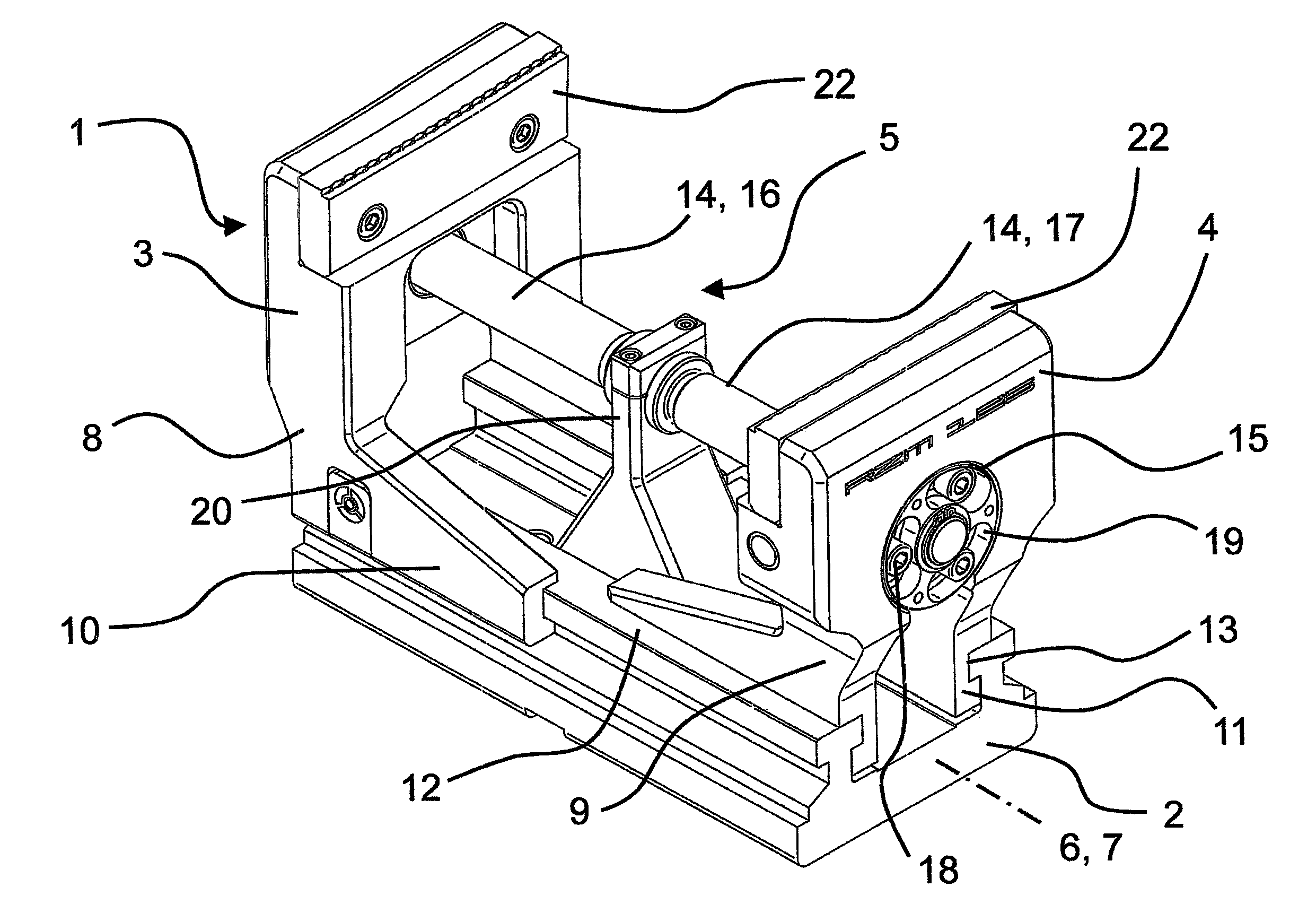
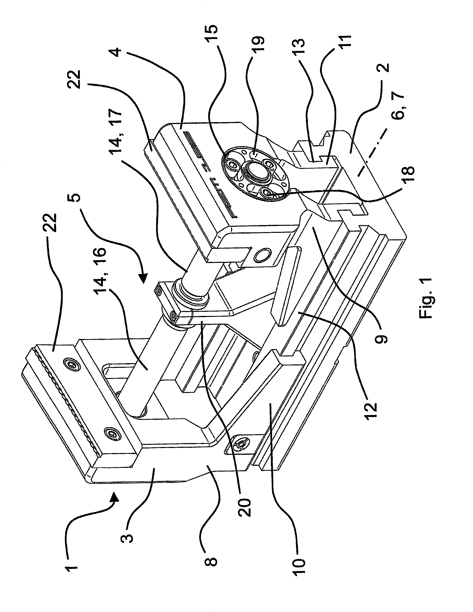
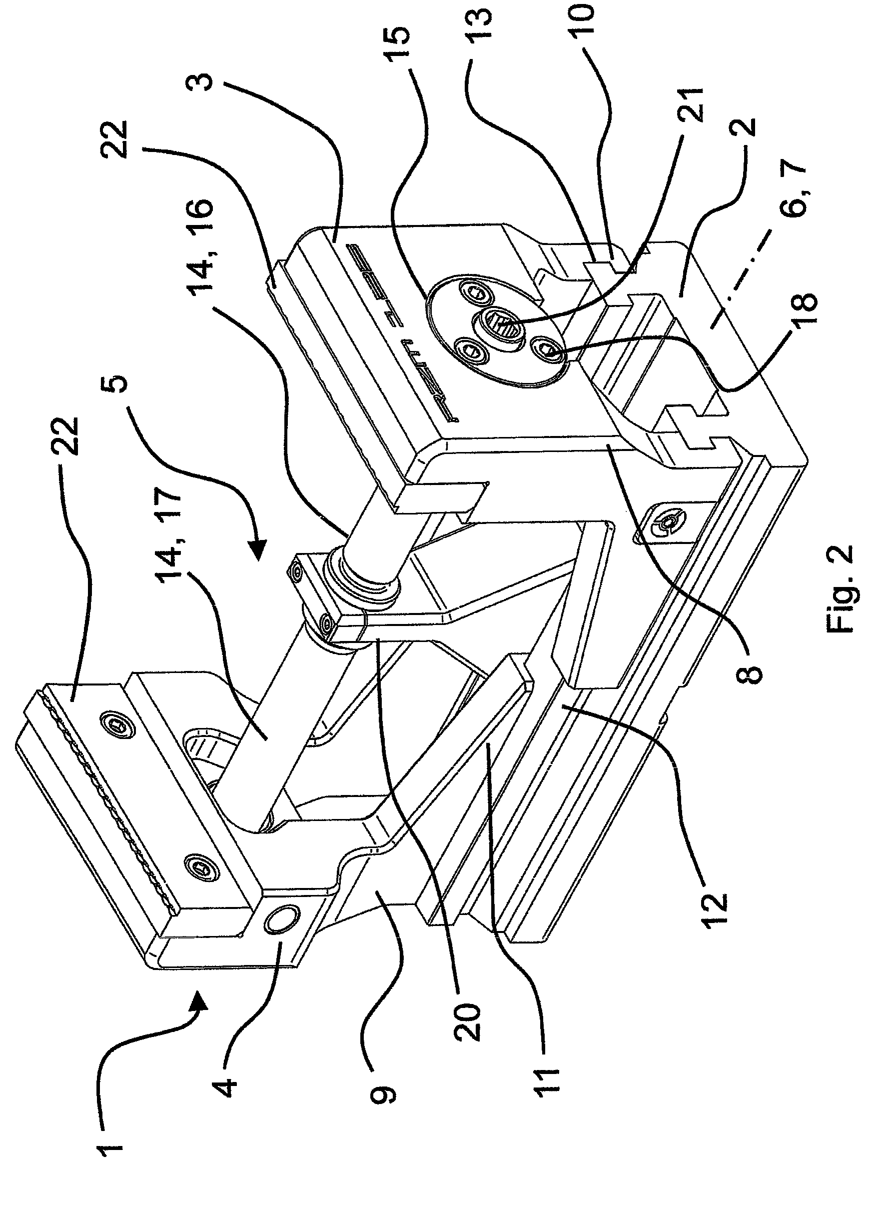
[0029]FIG. 1 shows a perspective view of a centric clamping vice 1 according to the invention, comprising a base support 2, on which a first jaw mount 3 and a second jaw mount 4 are adjustably supported along an adjustment path 7 oriented parallel to a longitudinal axis 6 with the aid of a spindle drive 5. First jaw mount 3 is guided on base support 2 by a first carriage 8, and second jaw mount 4 is guided on a second carriage 9. A pair of first slides 10 is assigned to first carriage 8, and a pair of second slides 11 is assigned to second carriage 9, the difference between the track width of first slides 10 and the track width of second slides 11 being greater than the width of second slides 11. The track widths of first slides 10 and second slides 11 are each defined by the distance between slides 10, 11. In the exemplary embodiment illustrated, the center axes of first slides 10 and second slides 11 are also congruent. When adjusting jaw mounts 3, 4 from the open position shown i...


PUM


Abstract

A centric clamping vice for centric clamping of workpieces is provided that includes a base support having a longitudinal axis, on which a first jaw mount, guided by a first carriage, and a second jaw mount, guided by a second carriage, are adjustably supported along an adjustment path oriented parallel to the longitudinal axis with the aid of a spindle drive. A pair of first slides is assigned to the first carriage, and a pair of second slides is assigned to the second carriage, and the difference between the track width of the first slides and the track width of second slides is greater than the width of second slides.

Description

[0001]This nonprovisional application claims priority under 35 U.S.C. §119(a) to German Patent Application No. 20 2013 103 810.5, which was filed in Germany on Aug. 22, 2013, and which is herein incorporated by reference.BACKGROUND OF THE INVENTION[0002]1. Field of the Invention[0003]The invention relates to a centric clamping vice for centric clamping of workpieces, comprising a base support having a longitudinal axis, on which a first jaw mount, guided by a first carriage, and a second jaw mount, guided by a second carriage, are adjustably supported along an adjustment path oriented parallel to the first longitudinal axis with the aid of a spindle drive.[0004]2. Description of the Background Art[0005]Centric clamping vices are known from the prior art and are illustrated, for example, in EP 1 946 890 A1, which corresponds to U.S. Pat. No. 8,020,877 (B2). In the centric clamping vices according to the prior art, however, it has proven to be disadvantageous that the clamping range p...

Claims


Application Information

Patent Timeline
Patent Type & Authority Patents(United States)
IPC IPC(8): B25B1/10B25B1/02B25B1/24
CPCB25B1/02B25B1/103B25B1/2405B25B1/2489
Inventor SCHWEIGERT, EDUARDBALLETSHOFER, STEFAN
Owner ROHM GMBH
Why Eureka
Try Eureka