Electromagnetic suction cup type multi-direction clamping caliper

An electromagnetic sucker and clamping technology, which is applied in the field of mechanical processing, can solve problems such as rigid installation position, flattened round pipe clamping, and lack of clamping and positioning, and achieve the effects of reducing installation and positioning errors, improving positioning and processing accuracy, and reasonable structure settings

Inactive Publication Date: 2018-11-16
黄柘屹
View PDF0 Cites 5 Cited by
  • Summary
  • Abstract
  • Description
  • Claims
  • Application Information

AI Technical Summary

Problems solved by technology

[0003] 1. The connection methods of flat vise and workbench in the prior art generally adopt bolt-fixed connection and pressure plate clamping connection, both of which have installation positions that are relatively rigid and the installation method is not flexible enough;
[0004] 2. The flat vise in the prior art is relatively strong when clamping plate-shaped parts, but it will not be clamped firmly when clamping cylindrical parts, and it is prone to slipping, especially when clamping tubular parts , due to the uneven force on the outer surface, it is very easy to clamp the round tube flat;
[0005] 3. When the part is clamped on the vise, there are no corresponding positioning references on both sides, and the clamping positioning is lacking, so it can only be used for rough positioning, and the positioning accuracy of the clamping is low

Method used


Image

  • Electromagnetic suction cup type multi-direction clamping caliper
  • Electromagnetic suction cup type multi-direction clamping caliper
  • Electromagnetic suction cup type multi-direction clamping caliper

Examples


Embodiment Construction

[0032] The following will clearly and completely describe the technical solutions in the embodiments of the present invention with reference to the accompanying drawings in the embodiments of the present invention. Obviously, the described embodiments are only some, not all, embodiments of the present invention. Based on the embodiments of the present invention, all other embodiments obtained by persons of ordinary skill in the art without making creative efforts belong to the protection scope of the present invention.

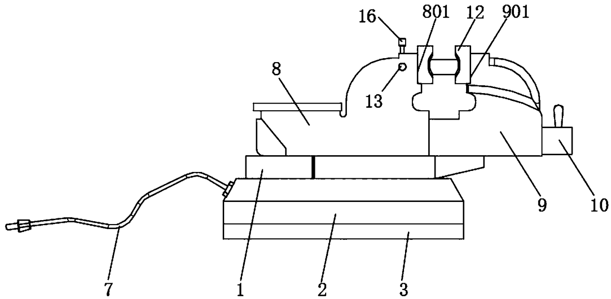
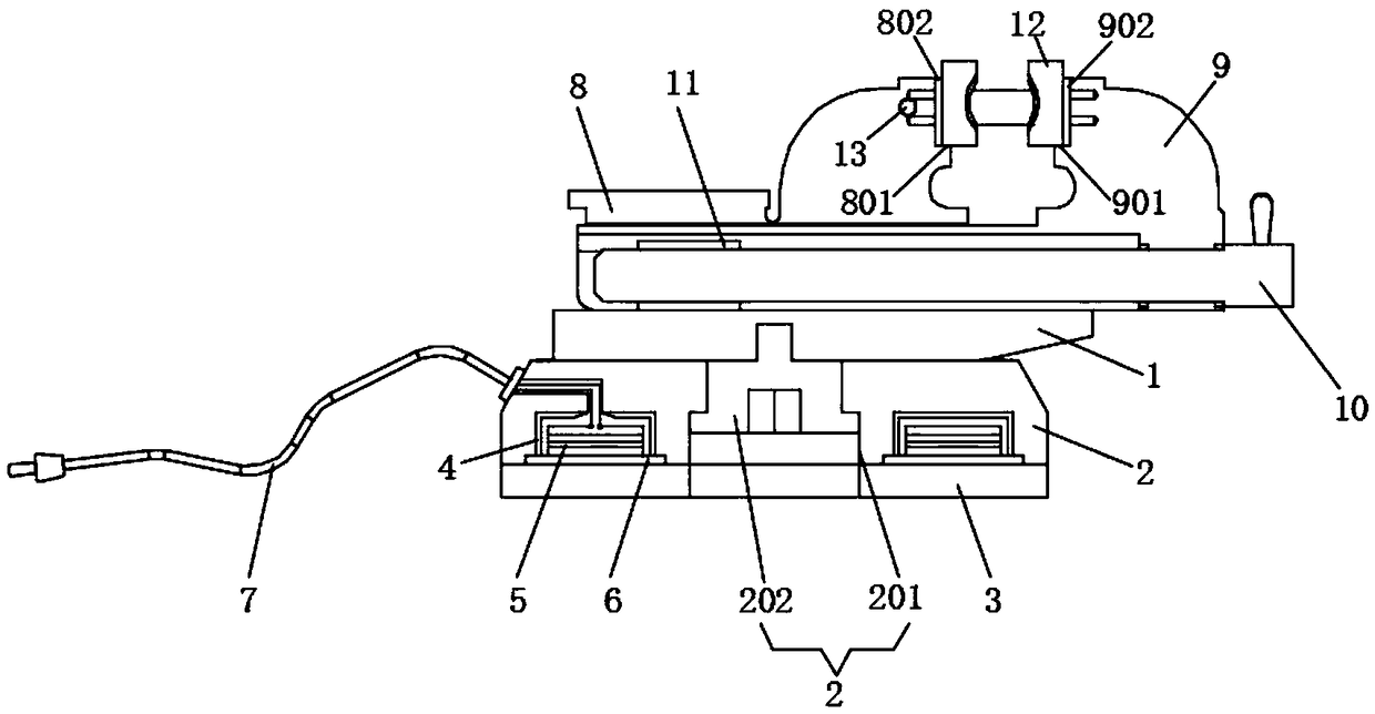
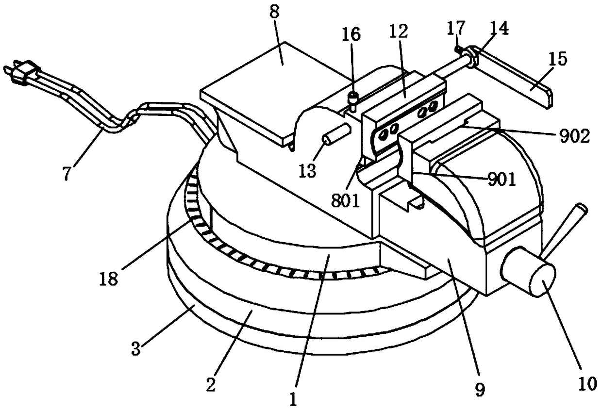
[0033] see Figure 1-8 , the present invention provides a technical solution: an electromagnetic chuck type multi-directional clamping caliper, including a turntable 1, a magnetic base 2 installed on the lower end of the turntable 1, a bottom plate 3 set at the lower end of the magnetic base 2, and a set at the upper end of the turntable 1. The fixed pliers body 8 and the movable pliers body 9 matched and connected on the right side of the fixed pliers body 8,...


PUM


Abstract

The invention discloses an electromagnetic suction cup type multi-direction clamping caliper. A rotating disk, a magnetic base installed at the lower end of the rotating disk in a matched manner, a bottom plate arranged at the lower end of the magnetic base, a fixed caliper body arranged at the upper end of the rotating disk, and a movable caliper body connected with the right side of the fixed caliper body in a matched manner are included; the body of the rotating disk is of a disk-shaped structure, and the fixed caliper body is arranged at the upper end of the rotating disk; the movable caliper body is installed at the right end of the fixed caliper body in a matched manner; the lower ends of the movable caliper body and the fixed caliper body are each a groove body of a U-shaped structure; a clamping block and the fixed caliper body form a fixed chuck, and the clamping block and the movable caliper body form a movable chuck; the fixed chuck and the movable chuck each correspondinglyhave three installing manners, and therefore the movable chuck and the fixed chuck form a multi-direction clamping manner, and the whole caliper is wider in clamping range; and due to a guiding rod,a guiding sleeve and a limiting plate arranged on the fixed caliper body, when a workpiece is clamped on the caliper, accurate positioning can be provided on the side face of the caliper, the installing and positioning error of the workpiece is lower, and the positioning and machining precision of the workpiece is improved.

Description

technical field [0001] The invention relates to the technical field of mechanical processing, in particular to an electromagnetic chuck type multi-directional clamping caliper. Background technique [0002] In the machining process, clamping equipment is often used. The most common clamping equipment is a flat vise. The flat vise is the main fixture for planers, milling machines, drilling machines, grinding machines, and slotting machines. It is widely used in milling machines, drilling machines, etc. Various planes, grooves, angles, etc. are processed. Machine vises are a general accessory of machine tools. They are used in conjunction with workbenches to fix, clamp, and position workpieces during processing, but they are used in actual use. There are still the following disadvantages: [0003] 1. The connection methods of flat vise and workbench in the prior art generally adopt bolt-fixed connection and pressure plate clamping connection, both of which have installation p...

Claims


Application Information

Patent Timeline
Patent Type & Authority Applications(China)
IPC IPC(8): B23Q3/06
CPCB23Q3/066
Inventor 黄柘屹王佳陈佳敏
Owner 黄柘屹
Why Eureka
Try Eureka