Clamp for milling machine machining

A milling machine processing and fixture technology, applied in the direction of manufacturing tools, metal processing equipment, metal processing machinery parts, etc., can solve the problems of vibration offset, drilling failure, easy damage to the workpiece, etc., to increase frictional resistance and increase clamping Range, the effect of preventing part offset

Active Publication Date: 2021-06-11
佛山市宝约五金制品有限公司
View PDF9 Cites 4 Cited by
  • Summary
  • Abstract
  • Description
  • Claims
  • Application Information

AI Technical Summary

Problems solved by technology

[0003] However, the existing fixtures for drilling circular parts generally use a bench vise to clamp the circular part, and the clamping of the bench vise generally causes the part to shift when drilling the part. Moreover, the clamping of the bench vise is generally easier to damage the surface of the workpiece, so excessive force should not be used during the clamping process, which will cause vibration and offset during the machining process, resulting in drilling failure, thereby increasing cost, reduce drilling efficiency

Method used


Image

  • Clamp for milling machine machining
  • Clamp for milling machine machining
  • Clamp for milling machine machining

Examples


Embodiment Construction

[0023] The following will clearly and completely describe the technical solutions in the embodiments of the present invention with reference to the accompanying drawings in the embodiments of the present invention. Obviously, the described embodiments are only some, not all, embodiments of the present invention. Based on the embodiments of the present invention, all other embodiments obtained by persons of ordinary skill in the art without making creative efforts belong to the protection scope of the present invention.

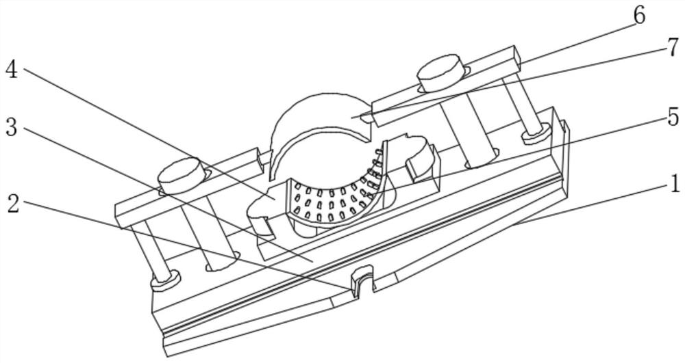
[0024] see Figure 1-6 , the present invention provides a technical solution: a fixture for milling machine processing, including a base 1, the center axis of the left and right sides of the base 1 is provided with a fixing groove 2, the purpose of setting the fixing groove 2 is to fix the fixture, the base 1 The top of the base is fixedly equipped with a support platform 3, the purpose of setting the support platform 3 is to place the clamp seat 4, the end of...


PUM


Abstract

The invention relates to the technical field of milling machine equipment, and discloses a clamp for milling machine machining. The clamp comprises a base, wherein fixing grooves are formed in the middle axes of the left side and the right side of the base, a supporting table is fixedly arranged at the top of the base, a clamping base is fixedly arranged at the end, away from the base, of the supporting table, a fixed arc clamping plate is fixedly arranged at the top of the clamping base, L-shaped lifting rods are fixedly arranged on the two sides of the top of the supporting table, and a movable arc clamping plate is arranged between the two L-shaped lifting rods. According to the clamp, the pressure generated in the part clamping process by the clamping plate is utilized, a transmission mechanism is arranged, the transmission mechanism can automatically transmit the pressure generated by the clamping plate to the part to a semicircular push rod, the semicircular push rod pushes out a friction ball, when the friction ball makes contact with the part, the contact area between the part and the clamping plate can be increased, and therefore the friction resistance of the part is increased, and the purpose of preventing the part from deviating in the drilling process is achieved.

Description

technical field [0001] The invention relates to the technical field of milling machine equipment, in particular to a clamp for milling machine processing. Background technique [0002] A milling machine is a machine tool with a wide range of uses. It can process planes (horizontal planes, vertical planes), grooves (key slots, T-shaped slots, dovetail slots, etc.), toothed parts (gears, spline shafts, sprockets), Spiral surface (thread, spiral groove) and various curved surfaces. In addition, it can also be used to process and cut off the surface and inner hole of the rotary body. When the milling machine is working, the workpiece is installed on the workbench or on the accessories such as the dividing head. , the rotation of the milling cutter is the main movement, supplemented by the feed movement of the table or the milling head, the workpiece can obtain the required processing surface, because it is multi-blade intermittent cutting, so the productivity of the milling mach...

Claims


Application Information

Patent Timeline
Patent Type & Authority Applications(China)
IPC IPC(8): B23Q3/00B23Q11/00
CPCB23Q3/00B23Q11/0032
Inventor 敬杨雪
Owner 佛山市宝约五金制品有限公司
Why Eureka
Try Eureka