Heat exchanger and deep well heat exchange system thereof

A technology of heat exchangers and heat exchange tubes, applied in indirect heat exchangers, types of heat exchangers, heat transfer modification, etc. Inconvenient and other problems, to achieve the effect of simple structure, convenient control, compact equipment

Active Publication Date: 2019-07-09
SHANDONG UNIV
View PDF11 Cites 15 Cited by
  • Summary
  • Abstract
  • Description
  • Claims
  • Application Information

AI Technical Summary

Benefits of technology

This patented technology allows for efficient cleanup of drilling wastewater from oil fields without causing environmental concerns such as pollution issues associated therewith. By controlling the amount of fluid injected into each section during drill bit cutting cycles, the process becomes more effective while minimizing damage caused by excessive pressure applied against sensitive areas within the borehole walls. Additionally, the use of thermally managed systems helps maintain consistence between temperature levels throughout the entire depth hole being drilled. Overall, these technologies improve the performance and safety of drills deployed deeper holes.

Problems solved by technology

Technological Problem addressed during this patented technical solution described in the patents describes various issues associated with current deep well mineral exploration practices such as overheated areas caused by excess temperatures or reduced oxygen levels. These factors affect the risk of explosion hazards when dealing with these conditions. Current solutions involve improving the design of the pipelines and pump stations within the minerals industry, including installing insulation materials between the pipe walls and ground level. However, there may still exist challenges like maintaining proper hydrous circulations through conduction paths without causing pressure waves from the fluids being transported.

Method used


Image

  • Heat exchanger and deep well heat exchange system thereof
  • Heat exchanger and deep well heat exchange system thereof
  • Heat exchanger and deep well heat exchange system thereof

Examples


Embodiment Construction

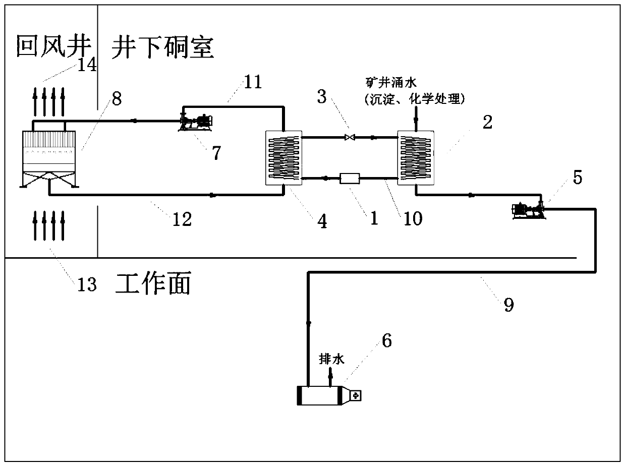
[0042] figure 1 A schematic diagram of the overall structure of a thermal system for deep mining is shown. Such asfigure 1 As shown, the thermal system of deep well mining includes three parts, which are the return air shaft part, the underground chamber part and the working face (mining area) part, in which the return air shaft part is equipped with a cooling tower 8, and the underground chamber part is equipped with an evaporator 2 , an expansion valve 3, a compressor 1 and a condenser 4, and the air cooler 6 is arranged on the working surface. The air cooler 6 is used to cool downhole air, and the evaporator 2, expansion valve 3, compressor 1, and condenser 4 constitute a refrigeration system; the cooling tower 8 and the condenser 4 constitute a circulation pipeline, and the air return shaft After the air in the cooling tower 8 exchanges heat with water, the water enters the condenser 4 through the pipeline, and exchanges heat with the refrigerant in the condenser 4. After...


PUM


Abstract

The invention provides a heat exchanger and a deep well heat exchange system thereof. The heat exchanger comprises a heat exchanger main body, a heat exchange tube, an inlet pipeline and an outlet pipeline; the heat exchange tube is arranged in the heat exchanger body, the inlet pipeline and the outlet pipeline are connected with the heat exchange tube, the heat exchange tube is characterized in that the heat exchange tube is an elastic tube bundle assembly, a bypass pipeline is arranged on the inlet pipeline, the pulse generation device is arranged on the bypass pipeline, the inlet pipeline and the bypass pipeline are respectively provided with main path valves and bypass valves, the pulsation flow needs to be generated and the size of the pulsating flow is determined through opening andclosing of the main path valves and the bypass valves. According to the heat exchanger and the deep well heat exchange system, the size of the opening degree of the bypass valves and the main path valves can be controlled, the pulsation flow and the size of the normal flow can be automatically adjusted, the heat exchange efficiency is improved, and the descaling effect is enhanced.

Description


Claims


Application Information

Patent Timeline
Owner SHANDONG UNIV
Why Eureka
Try Eureka