
A method of changing the magnetic flux of a motor

A technology of changing magnetic flux and magnetic flux, applied in the field of changing the magnetic flux of a permanent magnet synchronous motor, can solve the problems of limited adjustment range, decrease in reluctance torque, decrease in power density, etc., and achieve the effect of controllable change of magnetic flux.

Active Publication Date: 2021-07-30
SUZHOU AMTF ROBOTS CO LTD
View PDF0 Cites 0 Cited by
  • Summary
  • Abstract
  • Description
  • Claims
  • Application Information

AI Technical Summary

Problems solved by technology

However, the adjustment range is limited. In addition, this magnetic structure will inevitably lead to a decrease in the q-axis inductance Lq (the flux linkage on the motor rotor can be decomposed into two mutually perpendicular coordinates of the d-axis and q-axis), the reluctance torque decreases, and the power Density reduction

Method used


Image

  • A method of changing the magnetic flux of a motor
  • A method of changing the magnetic flux of a motor
  • A method of changing the magnetic flux of a motor

Examples


Embodiment 1

[0025] Example 1: Motor Magnetic Flux Structure of Iron Clear Cross Section and Size

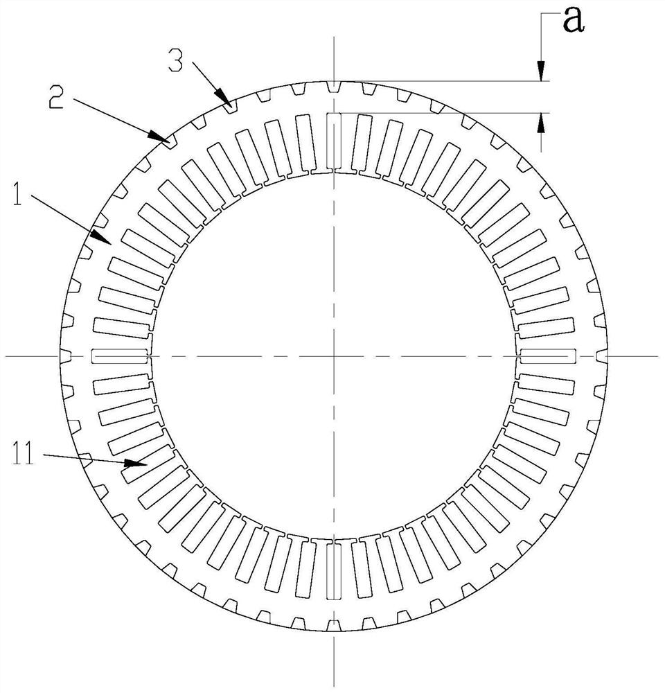
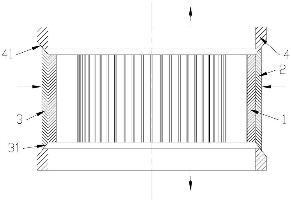
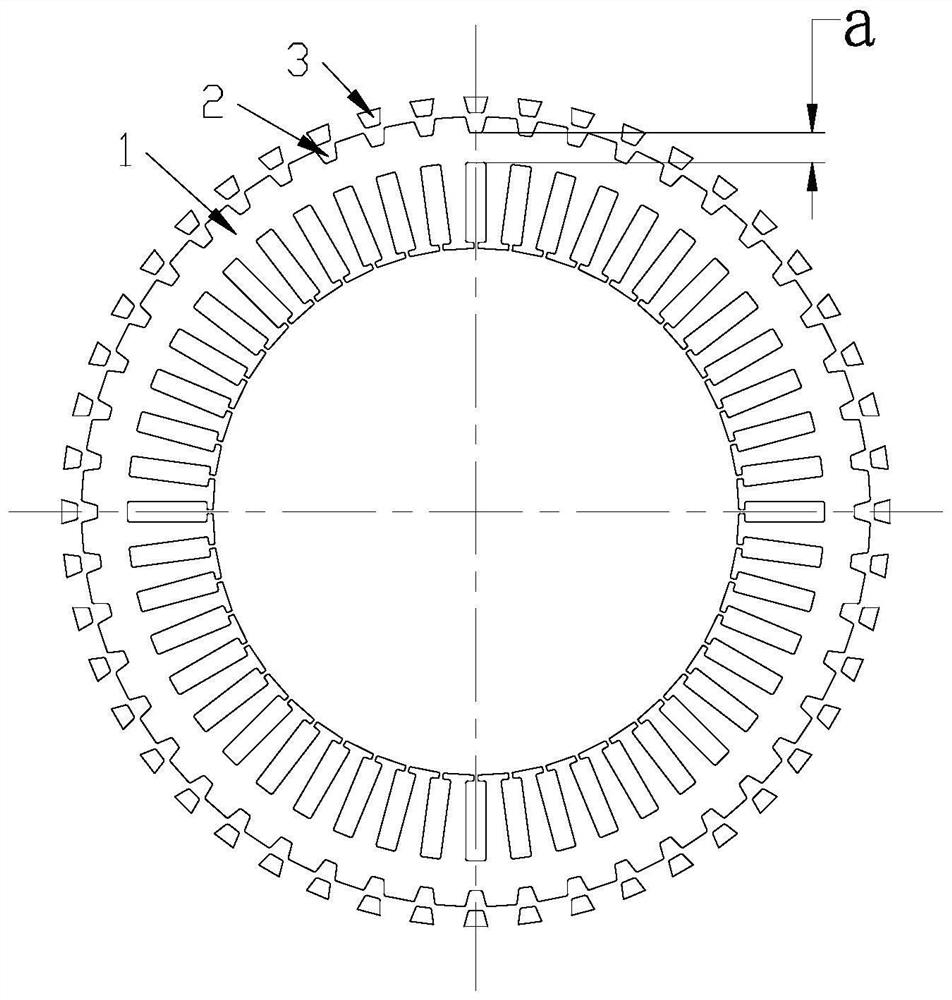
[0026] See figure 1 , 3 The migramid flux structure shown is shown, and the magnetic flux adjustment block 3 in the recess 2 can be embedded in the outer circumference of the iron core is provided on the stator core 1 of the open wired groove 11, and there is a respective end of the stator core. The two cone adjustment sleeves 4 are smaller than the tapered surface 41 of the stator axial direction tapered conditioning sleeve near the core end, and the diameter away from the end of the core is large.

[0027] The two ends of the magnetic flux adjustment block 3 have a tapered surface 31 that is in contact with the tapered tapered surface 41 of the two tapered regulating sleeves.

[0028] In order to keep the two end tapers 31 of the magnetic flux adjustment block 3 in contact with the two conical adjustment sleeves, the spring can be further provided, and the spring is provided, which makes the m...

Embodiment 2

[0032] Example 2: Motor change magnetic flux structure with variable gap size

[0033] See Figure 5 In the stator core 1 of the open wired groove 11, the slot 5 is embedded in the outer circumference of the iron core and inserted with the bottom surface of the slot slot, and both sides of the insert are gaps in both sides of the chute.

[0034] By moving insert circumferentially in the stator, the magnetoresistance size of the stator core is changed by changing the gap between the insert and the slide, thereby changing the stator magnetic flux.

[0035] The stator core is provided in the outer circumference of the insert regulating ring 7 that rotates about the axis of rotation, and the outer circumference of the insert 6 is fixed to the inner circumference of the insert adjustment ring 7. The outer weeks of the insert regulating ring 7 have two ring gear 9 meshing with the insert adjusting the gear shaft 8, and the insert adjusting the gear shaft 8 is connected to the output shaf...


PUM


Abstract

The invention provides a method for changing the magnetic flux of a motor, which is to change the effective magnetic flux of the motor by changing the magnetic permeability of the stator, and control the magnetic flux of the flux linkage of the motor to meet the requirements of low-speed, high-torque, high-speed, high-power, and high-efficiency of the motor. This method is to change the magnetic flux of the stator by changing the cross section of one or several parts of the stator flux linkage, thereby changing the magnetic flux of the motor.

Description

Technical field [0001] The present invention relates to a method of changing a magnetic flux of a motor, in particular a method of changing a magnetic flux of a permanent magnet synchronous motor. Background technique [0002] With the popularity and expansion of motor applications, the performance requirements of the motor have also improved, especially in the new energy transportation field, the motor requires high-torque at low speed, high-speed power, and in any case, high efficiency is required. And general motors are often difficult to achieve this requirement. Taking the permanent magnet synchronous motor as an example, if there is a large torque at low speed, the magnetic field strength of the rotor is very high, but the high magnetic field intensity is in the motor speed, and the self-inductive moving motion suppresses the motor speed, so that the motor cannot be High speed operation, for this purpose, we have to use weak magnetic control, namely, use a portion of the st...

Claims


Application Information

Patent Timeline
Patent Type & Authority Patents(China)
IPC IPC(8): H02K21/02
CPCH02K21/025
Inventor 林中尉门天珺
Owner SUZHOU AMTF ROBOTS CO LTD
Learn More