Cell contacting system for an electrochemical device

A contact system, electrochemical technology, applied in electrochemical generators, electrical components, batteries, etc., can solve problems such as functional limitations, and achieve the effect of simplified installation

Active Publication Date: 2019-07-09
ELRINGKLINGER AG
View PDF13 Cites 2 Cited by
  • Summary
  • Abstract
  • Description
  • Claims
  • Application Information

AI Technical Summary

Problems solved by technology

[0008]However, when the space provided between the unit terminals to be connected to each other is limited, the geometry of such balancing elements is strictly constrained, whereby make its functionality limited

Method used


Image

  • Cell contacting system for an electrochemical device
  • Cell contacting system for an electrochemical device
  • Cell contacting system for an electrochemical device

Examples


Embodiment Construction

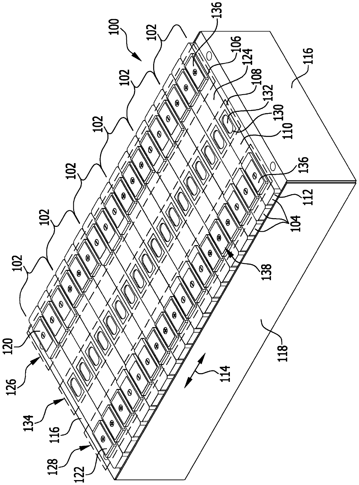
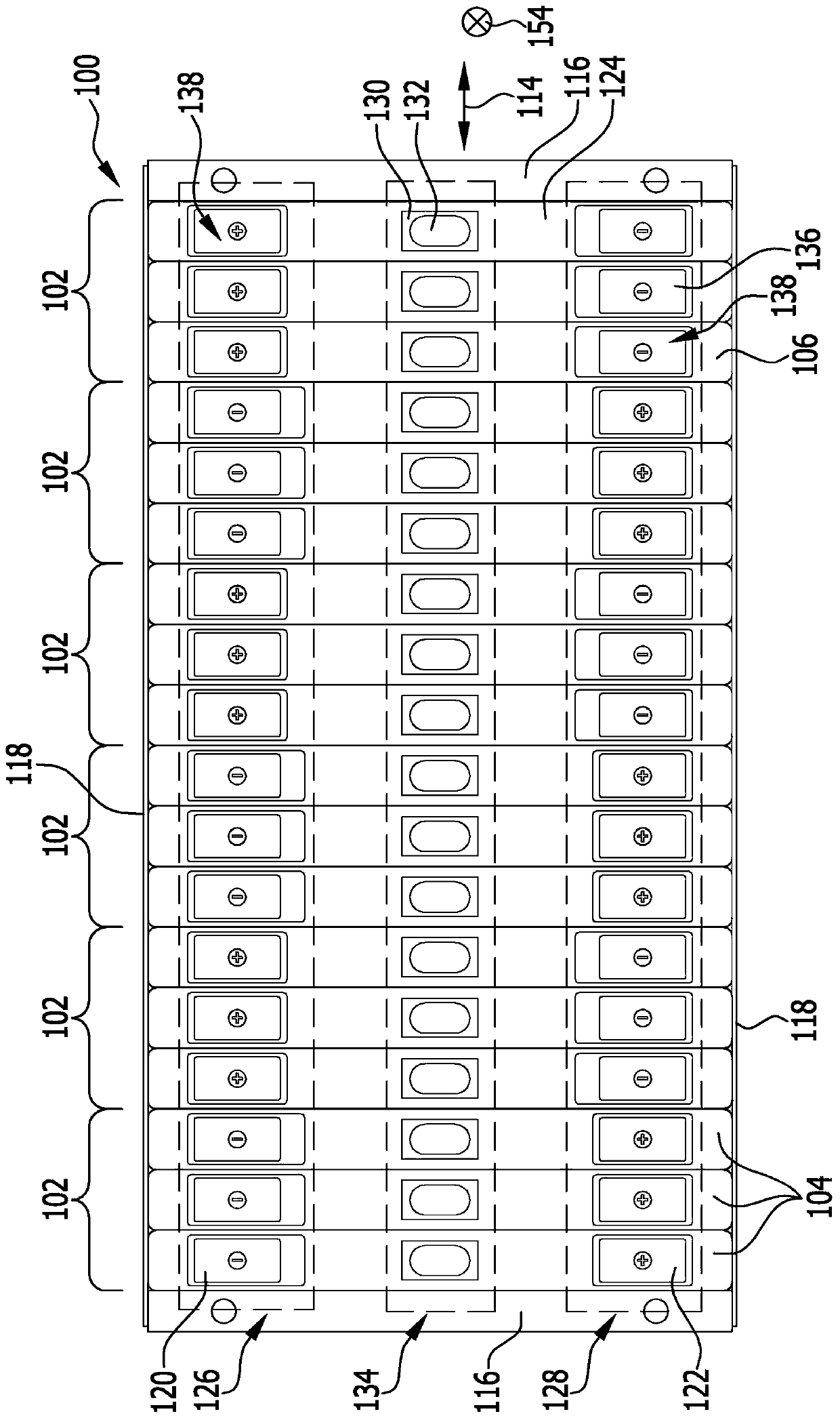
[0105] exist figure 1 and 2 The electrochemical device shown in , marked as a whole with 100, comprises a plurality, in the illustrated embodiment, six unit groups 102, each comprising a plurality, in the illustrated embodiment, respectively three The electrochemical unit 104.

[0106] Each electrochemical cell 104 has a prismatic, in particular substantially cuboid, housing 106, wherein the housing 106 each has two opposite wide sides 108, two opposite long sides A narrow side 110 and two respectively opposite short narrow sides 112 .

[0107] The electrochemical units 104 of an electrochemical device 100 such as a battery module are arranged successively along the longitudinal direction 114 of the electrochemical device 100, wherein every two electrochemical units 104 arranged successively along the longitudinal direction 114 have a width of one of them respectively. The side surfaces 108 bear against each other substantially flat and preferably substantially congruently....


PUM


Abstract

To create a cell contacting system for an electrochemical device comprising a plurality of cell groups, which each comprise one or more electrochemical cells, wherein each electrochemical cell has a first cell terminal and a second cell terminal, wherein the electrochemical cells follow each other along a longitudinal direction, the first cell terminals follow each other along the longitudinal direction in a first cell terminal region of the electrochemical device and the second cell terminals follow each other along the longitudinal direction in a second cell terminal region of the electrochemical device, wherein the cell contacting system comprises at least one cell connector for the electrically conductive connection of cell terminals of a first cell group to cell terminals of a secondcell group, which system also reliably permits a relative movement between the cell terminals to be electrically connected to each other even if the distances to the subsequent cell terminals are small, according to the invention at least one cell connector extends obliquely with respect to the longitudinal direction of cell terminals of the first cell group in the first cell terminal region to cell terminals of the second cell group in the second cell terminal region.

Description

technical field [0001] The invention relates to a cell contact system for an electrochemical device comprising a plurality of cell groups each comprising one or more electrochemical cells, wherein each electrochemical cell has a first cell terminal and a second cell terminal. two-unit terminal, wherein the electrochemical units are arranged successively along the longitudinal direction of the electrochemical device, [0002] the first cell terminals of the electrochemical cells are arranged one behind the other in the longitudinal direction in the region of the first cell terminals of the electrochemical device, and [0003] The second cell terminals of the electrochemical cells are arranged one behind the other in the longitudinal direction in the region of the second cell terminals of the electrochemical device, [0004] wherein the unit contact system comprises at least one unit connector for electrically conductively connecting unit terminals of the first unit group with ...

Claims


Application Information

Patent Timeline
Patent Type & Authority Applications(China)
IPC IPC(8): H01M2/10H01M2/20H01M10/052H01M2/12H01M2/30H01M50/528H01M50/209H01M50/503H01M50/51H01M50/522H01M50/55H01M50/553
CPCH01M2220/20Y02E60/10H01M50/30H01M50/503H01M50/553H01M50/209H01M50/249H01M50/509H01M50/522H01M50/55H01M50/51H01M50/502H01M50/543H01M50/20
Inventor 沃尔夫冈·弗里茨斯特凡·卡兹迈尔
Owner ELRINGKLINGER AG
Why Eureka
Try Eureka