Automatic self-adapted monitoring signal polarity laser control loop circuit

A technology for monitoring signals and controlling loops, which is applied to lasers, laser components, semiconductor lasers, etc., and can solve problems such as unfavorable delays and high circuit costs

Inactive Publication Date: 2005-03-23
DEUTSCHE THOMSON-BRANDT GMBH
View PDF1 Cites 0 Cited by
  • Summary
  • Abstract
  • Description
  • Claims
  • Application Information

AI Technical Summary

Problems solved by technology

This leads to disadvantageous delays when switching on the light source and requires high costs in the circuit

Method used


Image

  • Automatic self-adapted monitoring signal polarity laser control loop circuit
  • Automatic self-adapted monitoring signal polarity laser control loop circuit
  • Automatic self-adapted monitoring signal polarity laser control loop circuit

Examples


Embodiment Construction

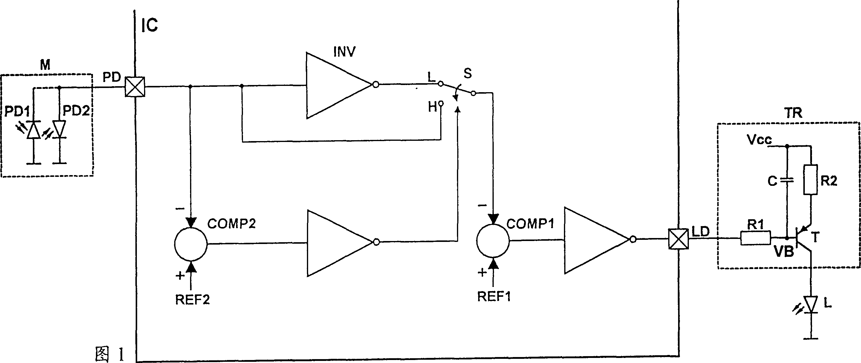
[0032]Figure 1 illustrates a block diagram of an optical power control loop for automatically adapting the polarity of the monitor signal, showing a monitor M fed to it at least a portion of the optical power for controlling the optical power or intensity of a light source L. The monitor M is formed by a photodetector which, depending on the type and connection of the photodetector, generates a positive or negative monitoring signal, the absolute value of which corresponds to the optical power of the light source L. The monitor M shown with a dotted box in Fig. 1 is two photodiodes PD1, PD2, the connection of their anode or cathode to the frame instructs the monitor M to generate a positive or negative monitor signal. The photodetector signal PD provided by the monitor M is fed to the input of the circuit IC for optical power control with automatic adaptation to the polarity of the monitor signal. In the area defined by the thick lines in Fig. 1 there is given a block diagram ...


PUM


Abstract

The present invention provides a method and a circuit device for a laser control loop, having automatic adaptation for monitoring signal polarity. SOLUTION: By utilizing a single step method, a signal which is generated by a monitor during the starting step of a laser control loop is compared with a reference value. On the basis of the result of the comparison, the signal generated by monitor is fed to a comparator which controls optical output of a laser during the start step of the laser control loop, directly or after inversion. An inverted monitoring signal is fed first to the comparator which controls an arbitrary output by a method, which is irrespective of monitoring signal polarity and depends on polarity of the reference value. Alternatively, the monitoring signal is fed directly, and a signal which feeds the monitoring signal through a non-inverted manner with regard to the monitoring signal reaching the reference value is generated.

Description

technical field [0001] The invention relates to a method and circuit arrangement of a laser control loop with automatic adaptive monitoring signal polarity. The laser control loop is used eg to control the optical power of a laser in an optical scanning system for recording or reproducing information independently of the laser monitor signal polarity and / or monitor diode polarity. Background technique [0002] It is known to control the optical power of light sources or lasers by feeding a portion of the transmitted optical power to so-called monitor diodes. For this purpose the light power or light intensity is measured by means of a light detector or a so-called monitor, usually formed by a photodiode or phototransistor or a light detector circuit, compared with a reference value, the light is controlled according to the result of the comparison power. Numerous photodetectors are known which differ in their design and with respect to the output signal they provide, for e...

Claims


Application Information

Patent Timeline
Patent Type & Authority Patents(China)
IPC IPC(8): G01R31/28G11B7/125G11B7/13H01S3/131H01S5/042H01S5/0683
CPCH01S5/0683H01S5/042G11B7/126H01S3/131
Inventor 斯蒂芬·莱尔鲁迪格·布伦海姆
Owner DEUTSCHE THOMSON-BRANDT GMBH
Why Eureka
Try Eureka