Brain focus target puncture positioning method and puncture positioning device thereof

A positioning method and a technology of a positioning device, which are applied in the medical field, can solve the problems that the puncture point cannot be objectively and accurately grasped, the treatment cost is high, and the operation quality and speed are affected, so as to improve the puncture accuracy and the success rate of the operation, and reduce the number of operations. Operation time and patient's pain, and the effect of excluding the influence of human factors

Pending Publication Date: 2019-07-12
杨俊
View PDF0 Cites 10 Cited by
  • Summary
  • Abstract
  • Description
  • Claims
  • Application Information

AI Technical Summary

Problems solved by technology

In the prior art, the surgical methods used to treat intracranial diseases mainly include craniotomy and puncture drainage. The former is more difficult, risky and expensive, and the latter is minimally invasive removal of intracranial hemorrhage or hematoma. It is clinically used because of its small trauma, safety and effectiveness, and low price. However, because the puncture point cannot be objectively and accurately grasped, and it is affected by human factors, the quality and speed of the operation are affected to a certain extent.
However, the various stereotaxic instruments currently used in clinical practice for skull puncture are complicated in structure, high in price, difficult to operate, and long in operation time, which increases the suffering of patients and limits their popularization and application.

Method used


Image

  • Brain focus target puncture positioning method and puncture positioning device thereof
  • Brain focus target puncture positioning method and puncture positioning device thereof
  • Brain focus target puncture positioning method and puncture positioning device thereof

Examples


Embodiment Construction

[0047] For better understanding and implementation, the technical solutions in the embodiments of the present invention will be clearly and completely described below in conjunction with the drawings in the embodiments of the present invention.

[0048] Unless otherwise defined, all technical and scientific terms used herein have the same meaning as commonly understood by one of ordinary skill in the technical field of the invention. The terms used herein in the description of the present invention are for the purpose of describing specific embodiments only, and are not intended to limit the present invention.

[0049] It should be noted that all directional indications (such as up, down, left, right, front, back, outside, inside...) in the embodiments of the present invention are only used to explain the direction of movement in a certain posture (as shown in the accompanying drawing). The relative positional relationship between the various components, the movement condition...


PUM


Abstract

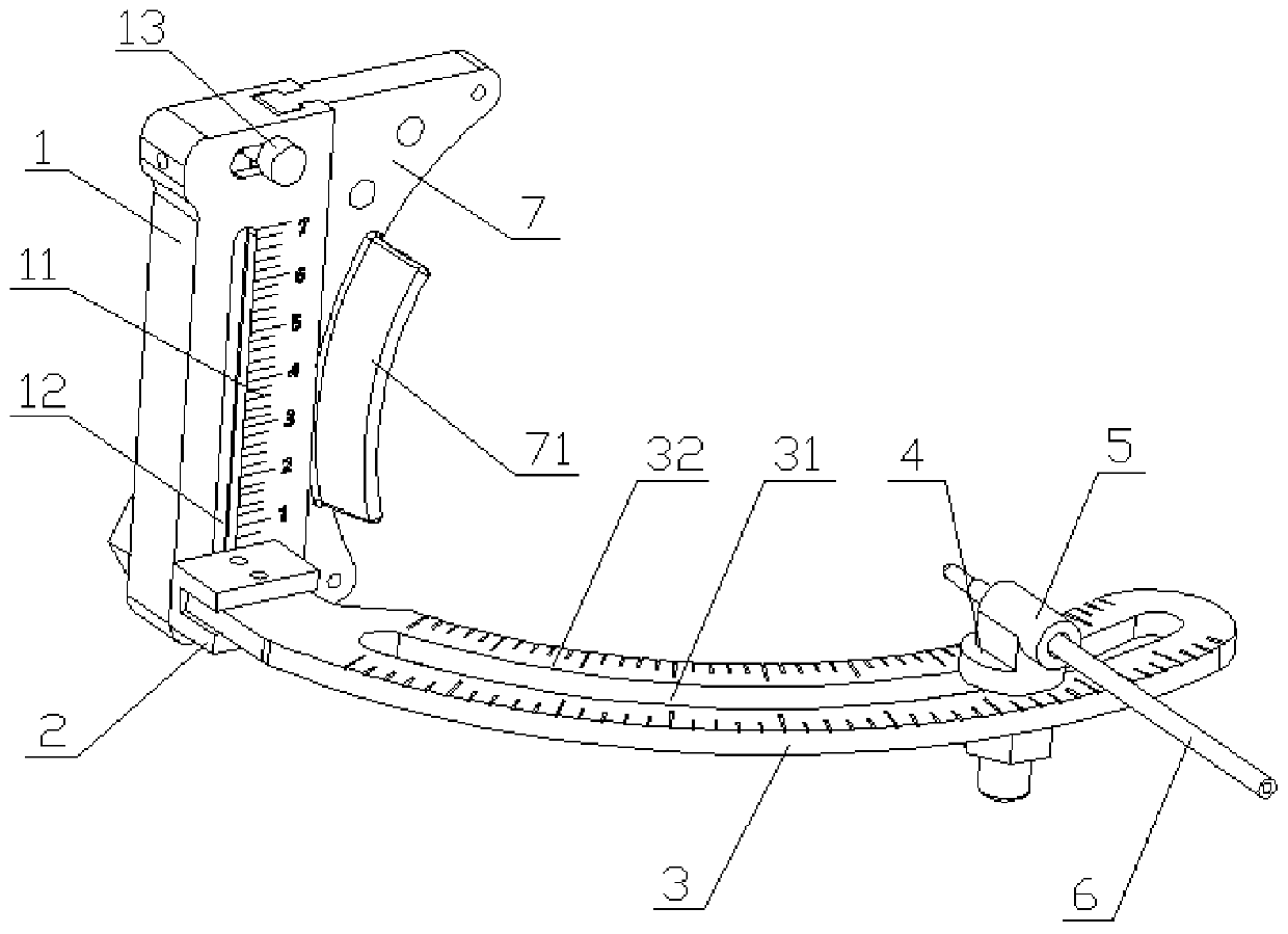
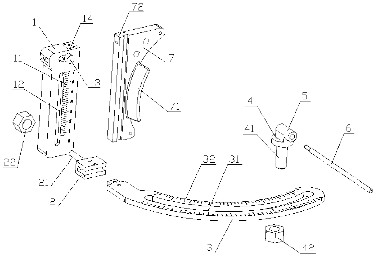
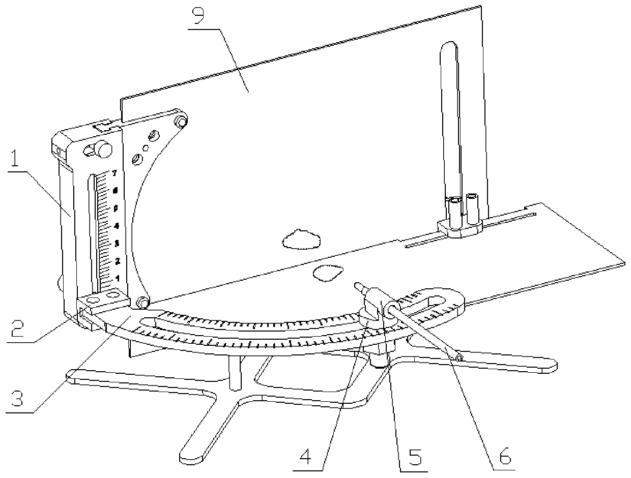
The invention provides a brain focus target puncture positioning method and a puncture positioning device. The puncture positioning device comprises a vertical positioning ruler, a first sliding baseand a horizontal positioning ruler, wherein the vertical positioning ruler is provided with first scales in the vertical direction; the first sliding base is vertically and slidably arranged on the vertical positioning ruler; the horizontal positioning ruler is arranged on the first sliding base. The puncture positioning method comprises the steps that a middle-line sagittal view surface of the brain of a patient is determined; brain CT scanning is carried out; CT scanning data is analyzed, and a target transverse-cutting layer image of a brain focus of the patient is determined; a middle-linesagittal image and the target transverse-cutting layer image are modeled in proportion, and simulated puncture is carried out; then solid puncture is carried out on the brain of the patient. The focus target puncture positioning method and the puncture positioning device thereof are used so that multi-point puncture positioning can be realized, the influence of human factors is eliminated, the puncture accuracy of a focus target and the success rate of an operation are improved, the operation difficulty is reduced, the operation time and the pain of the patient are reduced, and the method andthe device have high application and popularization significance.

Description

technical field [0001] The invention relates to the field of medical technology, in particular to a brain lesion target puncture positioning method and a puncture positioning device thereof. Background technique [0002] Diseases such as cerebral hemorrhage, brain abscess and brain cystic tumor are common clinical diseases in neurology. In the prior art, the surgical methods used to treat intracranial diseases mainly include craniotomy and puncture drainage. The former is more difficult, risky and expensive, and the latter is minimally invasive removal of intracranial hemorrhage or hematoma. It is clinically used because of its small trauma, safety and effectiveness, and low price. However, the quality and speed of the operation are affected to a certain extent because the puncture point cannot be objectively and accurately grasped, and it is affected by human factors. And the various stereotaxic apparatuses that are used in clinical practice for skull puncture at present, ...

Claims


Application Information

Patent Timeline
Patent Type & Authority Applications(China)
IPC IPC(8): A61B17/34A61B34/10A61B34/20A61B90/00
CPCA61B17/3403A61B34/10A61B34/20A61B90/06A61B2017/3407A61B2034/105A61B2034/107A61B2034/108A61B2034/2065A61B2090/062
Inventor 杨俊
Owner 杨俊
Why Eureka
Try Eureka