Electromagnetic ejection fencing roadblock machine

An electromagnetic ejection and fence technology, applied in the direction of fences, roads, roads, etc., can solve problems such as instability, low work efficiency, and single power

Pending Publication Date: 2019-07-12
深圳市链路电控实业有限公司
View PDF0 Cites 0 Cited by
  • Summary
  • Abstract
  • Description
  • Claims
  • Application Information

AI Technical Summary

Problems solved by technology

[0008] Therefore, the embodiment of the present invention provides an electromagnetic ejection fence ba...

Method used


Image

  • Electromagnetic ejection fencing roadblock machine
  • Electromagnetic ejection fencing roadblock machine
  • Electromagnetic ejection fencing roadblock machine

Examples


Embodiment Construction

[0027] The implementation mode of the present invention is illustrated by specific specific examples below, and those who are familiar with this technology can easily understand other advantages and effects of the present invention from the contents disclosed in this description. Obviously, the described embodiments are a part of the present invention. , but not all examples. Based on the embodiments of the present invention, all other embodiments obtained by persons of ordinary skill in the art without making creative efforts belong to the protection scope of the present invention.

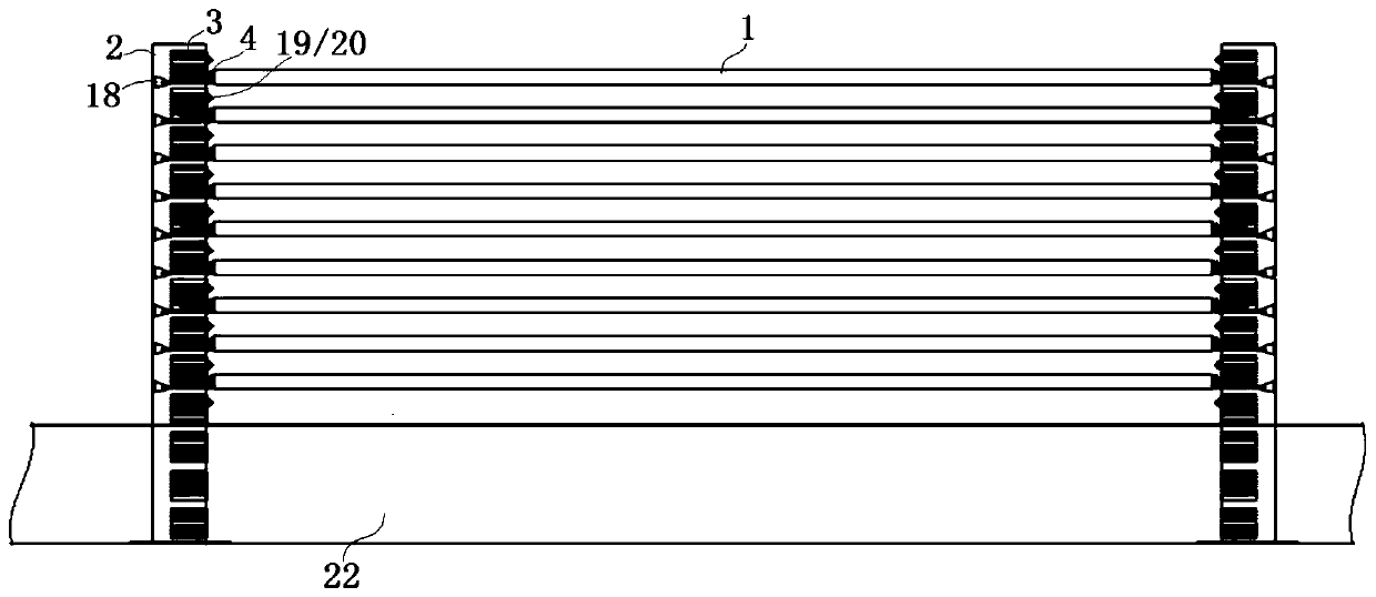
[0028] Such as figure 1 As shown, an electromagnetic ejection fence roadblock machine includes several rails 1, and the two ends of the rails 1 are symmetrically provided with an ejection body 2, and the inner surface of the ejection body 2 is provided with a magnetic rail 3, and the rails Both ends of 1 are provided with permanent magnet ejection blocks 4 matched with magnetic track 3 . The fe...


PUM


Abstract

The embodiment of the invention discloses an electromagnetic ejection fencing roadblock machine. The electromagnetic ejection fencing roadblock machine includes a plurality of crossbars, wherein ejection machine bodies are symmetrically arranged at the two ends of the crossbars, and magnetic tracks are arranged on the inner side faces of the ejection machine bodies; permanent magnet ejection blocks matched with the magnetic tracks are arranged at the two ends of the crossbars, wherein the magnetic tracks comprise magnetic track bodies; electromagnetic cavities are formed in the magnetic trackbodies, and groove openings connected with the electromagnetic cavities are formed in the inner sides of the magnetic track bodies; electromagnetic coil assemblies and position detection sensors are arranged in the electromagnetic cavities, and the electromagnetic coil assemblies and the position detection sensors are both electrically connected with a controller through wires; the inner ends of the permanent magnet ejection blocks are fixed parts, and the outer ends of the permanent magnet ejection blocks are sliding block parts; the fixed parts and the sliding block parts are fixedly connected through connecting plates, and the fixed parts are fixedly connected with the end parts of the crossbars; the sliding block parts are inserted into the electromagnetic cavities and are matched withthe electromagnetic cavities to slide, and the connecting plates penetrate through the groove openings; and permanent magnets which generate magnetic power with the electromagnetic coil assemblies are arranged on the sliding block parts.

Description

technical field [0001] The embodiment of the present invention relates to the technical field of fence products and roadblocks, and in particular to an electromagnetic ejection fence roadblock. Background technique [0002] In some special areas and occasions, such as customs, border inspection, warehouses, docks, ports, parking lots, road and bridge toll gates, community entrances and exits, etc., it is necessary to effectively control the flow of people and vehicles; and public institutions with anti-terrorism security needs, Confidential units, open exhibition halls, conference venues, and public ceremony venues, etc., require open office or display during the safe period, and emergency enclosures and other controls when there are security or anti-terrorism needs. However, due to the development of intelligent equipment, traditional single-drive roadblocks or electronic fences can no longer meet people's needs. Traditional roadblocks or electronic fences mainly have the f...

Claims


Application Information

Patent Timeline
IPC IPC(8): E01F13/04E04H17/14
CPCE01F13/048E04H17/14
Inventor 王文晖姚浩李传慧
Owner 深圳市链路电控实业有限公司
Why Eureka
Try Eureka